Engineering design
rat net
Resilient Atmospheric & Telemetry Network
A reference 666.0-meter autonomous rooftop link combining millimeter-wave data, coaxial optical tracking, independent sub-GHz recovery, and calibrated path-integrated precipitation sensing.
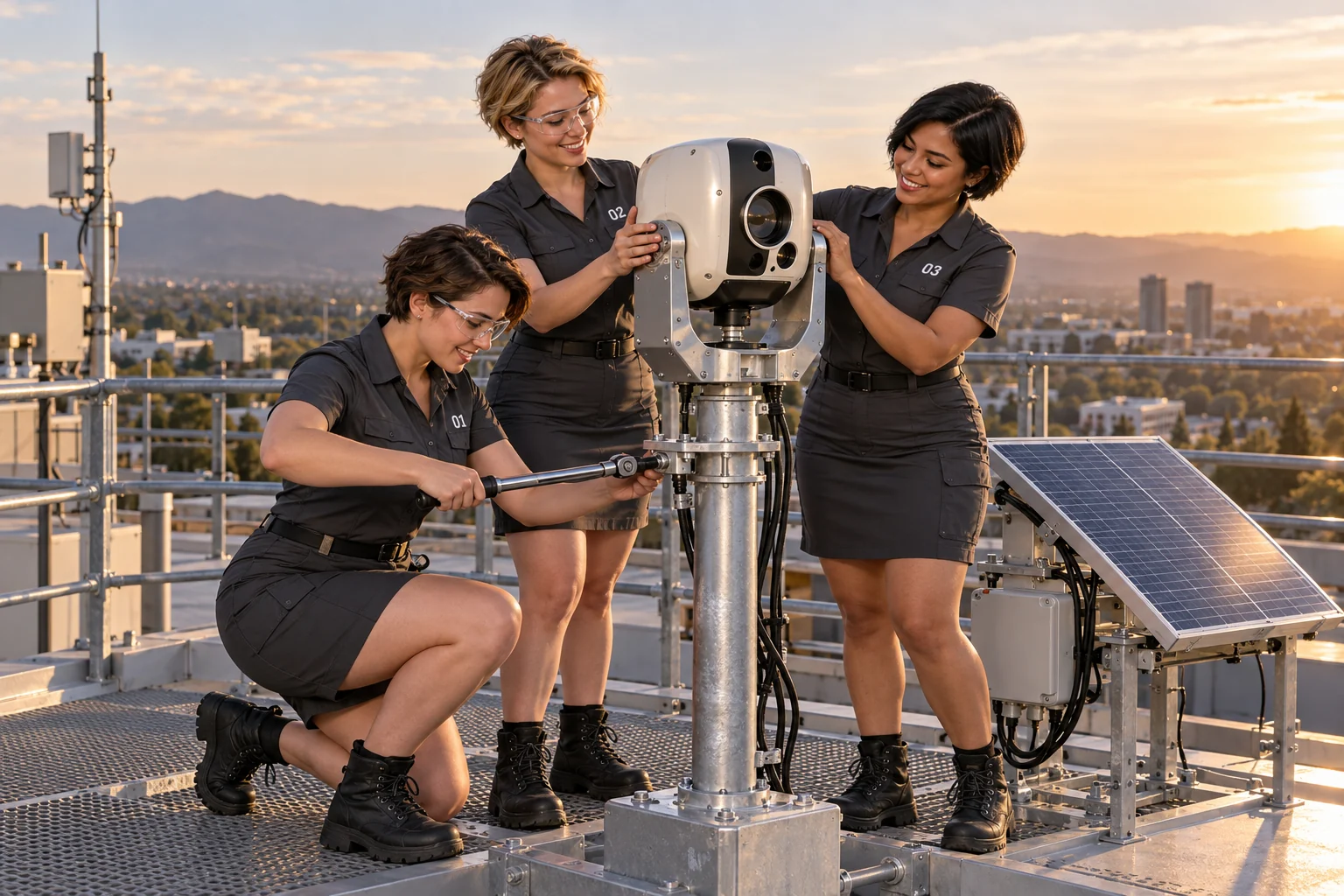
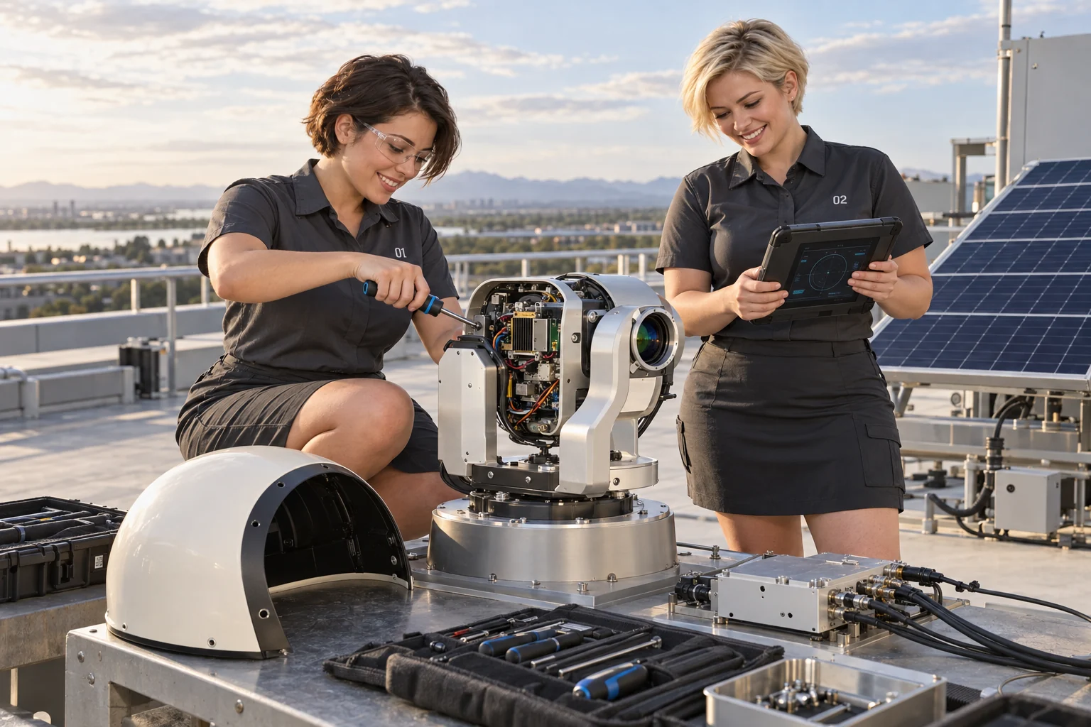
AI-generated concept illustrations · imagined adult staff, equipment and installation settings
Resilient Atmospheric & Telemetry Network
A 666.0-meter rooftop link that transports data, maintains its own alignment, and measures the atmosphere along its path.
Communication as a calibrated atmospheric instrument
rat net is an autonomous directional telecommunications terminal organized around three physically separated carriers: a V-band millimeter-wave data link, an 850 nm near-infrared alignment beacon, and a 915 MHz-band control link. Two identical terminals define a reference slant range of exactly 666.0 m. Actual deployment geometry must be surveyed, including elevation difference and uncertainty; the exact value is the design baseline rather than an assertion of perfect field metrology.
Reference values and the DCLXVI name. DCLXVI is the Roman numeral for 666. Ben chose the name primarily as a reminder to examine the locus of charge: LSM assigns fractional local charge contributions, with magnitudes such as 1/6 e and 1/3 e, rather than requiring each local contribution to be an integer multiple of e. The 666.0 m path and golden-ratio carrier are memorable placeholder inputs for a reproducible design case. Actual path length, frequency, bandwidth, and tolerances come from site survey, supported radio channels, applicable spectrum constraints, and measured link performance. The naming motif supplies no propagation advantage.
The V-band channel is both the high-capacity transport and the measurement path. Calibrated changes in path attenuation are inverted through ITU-R P.838-3 to estimate an attenuation-equivalent rain rate. The optical channel supplies directional error information independently of RF received power. The sub-GHz channel returns that error, carries mechanical telemetry, and coordinates recovery when optical tracking becomes unavailable. Additively manufactured Nylon 12 components provide enclosure geometry and experimental dielectric structures; machined aluminum and preloaded bearings establish the mechanical reference. [1]
The design separates three questions: Can the link carry traffic? Is its pointing observable? Can its attenuation be attributed to rain? An RF link can remain usable through an optical blackout while its rainfall estimate becomes invalid. Likewise, a perfectly tracked terminal can lose its high-rate modulation during a downpour. These conditions require different control actions and different data-quality flags.
“Orthogonal” describes independent frequency bands and control functions, not orthogonal RF polarizations or independent weather statistics. “Mesh” describes the intended routed network of multiple point-to-point edges. The two-terminal build is one edge; persistent mesh redundancy requires additional neighbors, radios and router interfaces.
Three carriers, one controlled line of sight
| Layer | Carrier and hardware | Function and interface |
|---|---|---|
| 1 · Data and weather | Ideal 61.8033988749894848204586834365 GHz; independent V-band modem | Multi-gigabit design objective; calibrated transmit/receive power, channel, beam state and modulation records. Native high-speed Ethernet bypasses the motion controller. |
| 2 · Alignment | 850 nm laser, 45° HR-Si combiner, silicon quadrant detector | Coaxial beacon injection; synchronous optical detection and calibrated differential pointing error. Sub-milliradian performance is an acceptance target. |
| 3 · Control and recovery | Semtech SX1262; 902–928 MHz band centered conceptually on 915 MHz | 50 Hz bidirectional telemetry using scheduled fast GFSK; lower-rate LoRa recovery profile when the fast channel cannot close. |
Editable Mermaid architecture
flowchart TD
  LAN["High-speed data LAN"] <--> RF["V-band modem and feed"]
  RF <--> SI["45 degree HR-Si combiner"]
  OPT["850 nm laser and receive optics"] <--> SI
  SI <--> PATH["Coaxial path: 666.0 m"]
  PATH <--> B["Remote RF and optical terminal"]
  B -- "Remote QPD errors" --> RB["Remote SX1262"]
  RB <-- "915 MHz-band telemetry" --> RA["Local SX1262"]
  RA <--> MCU["Teensy 4.1 controller"]
  OPT -- "Local QPD samples" --> MCU
  MCU -- "TMC5160 commands" --> G["Two-axis gimbal"]
  G -- "Encoders and IMU" --> MCU
  G -- "Pointing" --> SI
Coaxial integration and optical observability
The intended quasi-optical arrangement transmits RF through a high-resistivity float-zone silicon plate and reflects the 850 nm branch into the same boresight. The term RF transparent is a performance requirement. Silicon’s high refractive index produces substantial Fresnel reflection even when bulk loss is low. An optical dielectric high-reflector coating may improve NIR reflection, but its millimeter-wave effect must be measured. A continuous metallic mirror coating defeats the intended RF-through function. [5]
For a full-beam combiner, the plate belongs in a suitably sized collimated section or beam waist. Its projected clear aperture must encompass the RF beam without unacceptable truncation; at 45°, one plate dimension grows by 1/cos45° = √2. A sealed commercial radio does not expose that internal interface. The budgeted development route therefore evaluates a small external coaxial subaperture injector and measures its perturbation to the complete antenna pattern. That test is not proof of a full-aperture custom front end. The final geometry cannot be released merely by placing a mirror in front of a stock antenna.
Each terminal includes an optical transmit/receive separator, a narrowband 850 nm filter, a receive relay, a four-segment photodiode, four transimpedance channels and an ADC. Reciprocal beacons use separate modulation identifiers or time slots to reject local leakage. The proposed sensor images the entrance pupil onto the QPD so remote illumination displacement can be measured. An ordinary focal-plane tracker primarily measures incoming angle; its displacement is not automatically the remote transmitter’s pointing error. Pupil clipping, relay magnification, gimbal motion and finite beam curvature are included in the calibrated sensitivity matrix.
Real-time control and data-plane separation
The Teensy 4.1 runs the real-time controller on its 600 MHz Cortex-M7. Its built-in Ethernet is 10/100 Mbit/s; it does not forward the multi-gigabit payload. Traffic passes directly between the V-band modem and a suitable 2.5/10GbE or SFP+ site interface. The MCU logs sensor states, drives two TMC5160 motor channels, reads two output-shaft AS5048A encoders, and acquires mast orientation/rates from a BNO085. [6] [7] [8] [9]
Place the IMU on the fixed mast reference, away from motor and encoder magnets. Use gyro-based short-term orientation and calibrated coordinate transforms for sway feedforward; magnetometer heading near steelwork is not a precision pointing reference. A single IMU measures rotation and acceleration, not drift-free absolute mast-tip translation. Endpoint translation and unmodeled structural bending remain observable through the optical link while locked.
Proposed scheduler: 1 kHz local encoder/motion loop, 100–200 Hz IMU updates where supported by the selected report, synchronous optical acquisition and 50 Hz filtered QPD reports, 50 Hz remote outer-loop updates, and approximately 1 Hz published weather estimates with raw data retained. Freshness checks, sequence numbers, CRC and authenticated control messages prevent stale or unauthorized commands from entering the servo.
50 Hz telemetry that fits the radio
The SX1262 supports LoRa and FSK, with a manufacturer-stated maximum FSK rate of 300 kbit/s. The baseline uses 200 kbit/s GFSK, a 20 ms TDD superframe and one packet per terminal per superframe. A proposed 48-byte application payload carries timestamp/sequence, QPD X/Y and sum, compressed IMU attitude/rates, both 14-bit encoder values, health bits, and authentication data. Assuming 12 additional bytes for preamble, sync, length and CRC, each 60-byte transmission occupies 2.4 ms; both directions consume 4.8 ms before switching, hop and guard intervals. Payload packing and measured radio turnaround determine the final slot allocation. [10]
For comparison, a 48-byte LoRa packet at SF7, 125 kHz bandwidth, coding rate 4/5, explicit header, CRC and eight preamble symbols occupies approximately 97.536 ms. It cannot support this bidirectional 50 Hz schedule. LoRa is a degraded-rate rendezvous/recovery mode; entry is scheduled with a common epoch or deterministic timeout so the two ends cannot strand each other on different PHYs.
“915 MHz” denotes the regional band, not unrestricted continuous transmission on one high-power channel. The proposed fast profile uses a compliant frequency-hopping plan within 902–928 MHz. Under 47 CFR §15.247(a)(1)(i), a hopping channel below 250 kHz 20 dB bandwidth requires at least 50 hopping frequencies and no more than 0.4 s occupancy per channel in 20 s; at 250–500 kHz it requires at least 25 frequencies and no more than 0.4 s in 10 s. Proposed use: 50 evenly used hopping channels, spacing at least the measured 20 dB bandwidth, with band-edge guards. At 50 packets/s and 2.4 ms/packet, occupancy averages 0.048 s/channel per 20 s per transmitter. Spectral width, emissions and each PHY profile require measurement and an applicable equipment authorization. [4]
Close the RF budget, then close the measurement model
Reference geometry and free-space loss
Use c = 299,792,458 m/s exactly, f0 = 61.8033988749894848204586834365 GHz and d = 666.0 m = 0.6660 km. Numerical outputs are rounded to meaningful engineering precision. These are the declared placeholder inputs for this worked example; substitute the surveyed distance and selected supported carrier, then recompute the budget before deployment.
LFS = 20 log10(4πdf/c) = 124.737515 dB
LFS[dB] = 92.447783 + 20 log10(f[GHz]) + 20 log10(d[km])
At exactly 61.000 GHz, FSPL is 124.623865 dB, only 0.113650 dB lower. Atmospheric absorption changes with frequency much more structurally than this geometric term. The requested oxygen-band planning assumption is γO₂ = 12 dB/km:
The 12 dB/km value is an adopted budget input, not a universal oxygen constant. Compute operational gas loss from ITU-R P.676-13 using actual frequency, pressure, temperature and water-vapor content. For a multi-gigahertz channel, evaluate the frequency dependence across the occupied spectrum; a center-frequency approximation can conceal substantial oxygen-band curvature. [2]
Survey the first Fresnel zone, not just visual line of sight. The 60% clearance figure is an initial siting criterion; roof edges, parapets and moving vegetation require a measured multipath check.
Worked high-rate design case
The following parameters are explicit design assumptions. They are not vendor specifications for the commercial radio used in the BOM.
| Budget term | Value | Meaning |
|---|---|---|
| Conducted transmit power PT | +10.00 dBm | Average power at the defined RF reference plane |
| Transmit gain GT | +40.00 dBi | Realized gain before separately itemized external losses |
| Receive gain GR | +40.00 dBi | Same reference convention at both ends |
| Free-space path loss | −124.738 dB | Ideal carrier; 666.0 m |
| Oxygen planning loss | −7.992 dB | 12 dB/km input |
| Two combiner assemblies | −2.00 dB | 1.00 dB per terminal, including coating and supports; must be demonstrated |
| Dry radome / external aperture loss | −1.00 dB | 0.50 dB per terminal |
| Residual pointing / implementation allowance | −1.00 dB | Combined link allowance |
| Clear-sky receive level PR,0 | −46.730 dBm | Before additional weather losses or unbudgeted gas correction |
| Assumed high-rate receive threshold | −60.00 dBm | Must be verified at the selected modulation and packet-error criterion |
| High-rate clear-sky margin | 13.270 dB | Available for rain, wet surfaces and additional uncertainty |
| Assumed robust-mode threshold | −68.00 dBm | Lower throughput; gives 21.270 dB nominal margin |
M = PR − Pthreshold.
A 40 dBi aperture with assumed efficiency η = 0.55 requires approximately D = λ√(10G/10/η)/π = 0.208 m. At 2.16 GHz noise bandwidth and 7 dB noise figure, −174 + 10log10(2.16×10⁹) + 7 ≈ −73.66 dBm. The assumed −60 dBm high-rate threshold implies about 13.66 dB SNR; actual coding, implementation loss and error-rate requirements determine whether it is sufficient.
At 915 MHz the same free-space baseline gives 88.146 dB loss. An illustrative +14 dBm control transmitter with 2 dBi antennas at both ends and 2 dB combined cable loss predicts −72.146 dBm before rooftop fading. Compare that with measured fast-GFSK sensitivity; long-range LoRa sensitivity is not applicable to this budget.
Regulatory operating envelope
47 CFR §15.255 governs the 57–71 GHz band. Section (c)(1)(i) permits 40 dBm average / 43 dBm peak EIRP; the outdoor fixed point-to-point alternative in (c)(1)(ii) permits up to 82/85 dBm, reduced by 2 dB for each dB of antenna gain below 51 dBi, with the stated floor. At 40 dBi, that alternative evaluates to 60/63 dBm. Section (e) also limits peak conducted power, normally to 500 mW for these communication devices. The example’s nominal pre-loss average EIRP is 50 dBm, requiring the fixed-link provision rather than the general 40 dBm envelope. Peak power must be checked separately. [3]
Use the specific authorized antenna configuration; custom combiner, lens or radome modifications require a compliance assessment. Opportunistic RSSI-based meteorology does not automatically establish the equipment’s regulatory classification. This design assumes a communications-link authorization; a radar or field-disturbance-sensor implementation would require its own applicable limits. The FCC provisions are regulations; ITU-R P.838 is a propagation recommendation, not an authorization to transmit.
Rain inversion and the quantity actually measured
ITU-R P.838-3 defines specific rain attenuation γR = kRα, with γR in dB/km and R in mm/h. Select k and α for carrier frequency, polarization and path elevation. Evaluation of its continuous coefficient functions at f0 gives the following rounded values. [1]
| Polarization on a horizontal path | k | α |
|---|---|---|
| Horizontal | 0.893800 | 0.759271 |
| Vertical — worked weather case | 0.885288 | 0.742973 |
Req(t) = [Arain(t)/(kd)]1/α = [(1/d)∫0dR(s,t)αds]1/αDistances in these integrals are in kilometers. For spatially uniform rain, Req equals the actual rain rate.
The observable is a line integral of Rα. Because α ≠ 1, its inverse is not generally the arithmetic path-mean rain rate. Publish corrected attenuation and Req, together with uncertainty and flags. A single path cannot resolve where rain occurred along the 666 m segment; spatial reconstruction needs multiple intersecting links and a stated inversion model.
α = [kHαH + kVαV + (kHαH − kVαV)cos²θ cos(2τ)]/(2k)θ is elevation and τ is polarization tilt relative to horizontal. Use actual geometry and polarization at each RF configuration.
| Uniform rain, mm/h | Vertical rain loss, dB | High-rate margin, dB |
|---|---|---|
| 1 | 0.590 | 12.681 |
| 5 | 1.949 | 11.321 |
| 10 | 3.262 | 10.008 |
| 25 | 6.445 | 6.826 |
| 50 | 10.786 | 2.485 |
| 100 | 18.051 | −4.781 |
| 150 | 24.397 | −11.126 |
Calculated at the ideal carrier for uniform rain; WAA and additional environmental losses are excluded. Negative high-rate margin does not by itself imply complete link loss.
The nominal high-rate rain-only margin closes at approximately 66.1 mm/h. Reserving 3 dB for wet surfaces and remaining uncertainty reduces that value to about 46.8 mm/h. These are deterministic budget intersections, not an annual availability prediction. Local rain statistics, gas conditions, correlated outages and measured receiver thresholds are required for an availability claim.
Calibration and wet antenna attenuation
Work in calibrated loss coordinates, with transmit power and receive power referenced consistently. Define L(t) = PT,cal(t) − PR,cal(t), and fit a dry reference Ldry for frequency, temperature, beam state and pointing. Subtract only corrections that are not already included in that reference:
- Characterize the receiver. Sweep known attenuation at stable geometry; identify RSSI nonlinearity, quantization, AGC transitions, transmit-power reporting error and measurement latency. Record modulation and antenna beam changes. A proprietary RSSI display is not a calibrated power meter.
- Fit dry behavior. Acquire at least one full day/night thermal cycle, ideally several dry days. Establish temperature-dependent RF/optical boresight offsets and slow dry-reference drift. Freeze baseline adaptation during suspected precipitation so rain is not learned away.
- Measure each wet surface independently. With the propagation path otherwise dry and alignment fixed, wet A’s radome/combiner aperture in controlled repeatable stages and record excess loss through drying. Repeat at B, then both. Distinguish water films, droplets, drainage orientation and temperature. Keep the spray out of the free-space measurement path.
- Fit a causal WAA model. A candidate wetting model is dAWAA/dt = (A∞(w,T) − AWAA)/τwet; drying uses dAWAA/dt = −AWAA/τdry. Fit parameters per terminal and surface treatment, using local wetness sensors as inputs. This is an empirical correction, not part of P.838.
- Validate on held-out storms. Compare with calibrated reference gauges or a disdrometer and, where available, radar context. A gauge at one endpoint is a point sample and cannot prove path-mean accuracy under nonuniform rain. Report separate dry, wetting, sustained-rain and drying errors.
Two endpoint wetness sensors constrain the correction but do not make it unique. Bidirectional RF readings share much of the same rain and WAA loss; they cannot independently identify two wet antennas and path rain without additional assumptions. Dense fog, steam, snow and ice are separate regimes. ITU-R P.840 supplies a microwave cloud/fog model, not an 850 nm extinction law. [11]
If channel bandwidth is large or the radio hops between centers, process per-channel/per-subcarrier power where possible. In general, averaged received power is an integral of PT(f)|H(f)|²10−A(f)/10, not the power corresponding to arithmetic mean attenuation. A single-frequency rain inversion is then an approximation requiring calibration.
For σA = 0.2 dB, the attenuation-only relative uncertainty is about 45.7% at 1 mm/h and 8.25% at 10 mm/h. Near zero excess attenuation, publish a detection limit or “below threshold,” not a signed rainfall estimate. When the receiver falls below sensitivity, record a censored observation: attenuation exceeds a bound. Do not convert the RSSI floor into a precise rain rate.
Quadrant differential math and the remote pointing loop
Label the QPD A upper-left, B upper-right, C lower-left and D lower-right. Let qi be gain-corrected, dark-subtracted, synchronously demodulated photocurrent. Reject saturation and low-sum samples before normalization:
ΔX = [(qB + qD) − (qA + qC)]/S
ΔY = [(qA + qB) − (qC + qD)]/S.
For an ideal untruncated Gaussian spot with 1/e² intensity radius w at the detector, ΔX = erf(√2x/w), so x = (w/√2)erf−1(ΔX), and near center x ≈ w√πΔX/(2√2). Finite quadrants, gaps, pupil clipping and relay distortion invalidate a universal scale factor. Calibrate a two-axis map at the actual geometry rather than assuming a QPD voltage directly equals milliradians.
δθ̂A = JBA−1(δqB − JBBδθB)q = [ΔX, ΔY]ᵀ. Identify the Jacobians by moving one calibrated axis at a time. A poorly conditioned J rejects the optical arrangement as a transmitter-pointing sensor.
For direct measurement of transverse beam-center displacement at the far endpoint, δθ ≈ δx/d: 0.1 mrad corresponds to 66.6 mm at 666.0 m. For an angular focal-plane receiver the relation is instead δθ ≈ δx/feff. These two measurement geometries must not be interchanged. Reciprocal loops require agreed coordinate transforms and either a decoupled calibration or alternating excitation during acquisition.
A Gaussian beacon trade study uses w(d)² ≈ w0² + (βd)², with β the far-field half-angle. At β = 0.25 mrad, the far-end radius is approximately 166.5 mm when the initial radius is negligible. A centered circular receive aperture of radius 25 mm captures about 1 − exp[−2(25/166.5)²] = 4.41% before optical and atmospheric losses. This example sets an acquisition scale; it does not set laser power or prove centroid observability under clipping.
The near-IR source is invisible and the expanding/searching beam is part of the product’s accessible emission. Specify a Class 1 accessible-emission design objective, a hardware enable/interlock and bounded search envelope. Class is determined for the completed optical assembly under IEC 60825-1 and the applicable FDA laser-product framework, not inferred from a bare diode’s nominal power. [16]
G(s) ≈ ωn²s² + 2ζωns + ωn²
Htrack(s) = C(s)G(s)e−sτ1 + C(s)G(s)e−sτ.
G is the identified inner position-loop response; τ includes optical processing, packet scheduling, radio transit and task latency. Use derivative filtering, integrator anti-windup, velocity/acceleration limits and bumpless mode transitions. The initial remote-loop crossover target is 1–3 Hz, with measured phase margin ≥45° and gain margin ≥6 dB. A 40 ms delay alone contributes 43.2° phase lag at 3 Hz. A 50 Hz packet rate does not justify a 25 Hz steering bandwidth.
θPID[n] = KPe[n] + I[n] + Dfiltered[n].
The two NEMA 17 axes use nominal 1.8° full-step motors and 50:1 strain-wave reducers. Output full-step increment is 0.036° = 0.628319 mrad. At 256 microsteps the command increment is 2.454 μrad. AS5048A output-shaft resolution is 2π/16,384 = 0.383495 mrad/count. Neither microstep size nor encoder resolution guarantees accuracy. “Zero backlash” excludes geometric gear clearance; torsional compliance, hysteresis, bearing runout and encoder nonlinearity remain. Optical feedback supplies the fine reference, while calibrated encoders support bounded recovery. [7] [8] [12]
Proposed locked-state acceptance is ≤0.30 mrad RMS per axis under a specified wind/thermal test, measured by independent metrology or a validated optical calibration. Encoder-only recovery is not assumed to meet that accuracy.
Print the geometry. Machine the references. Measure the interfaces.
The fabrication route uses the Formlabs Fuse X1 with qualified Nylon 12 settings and a precision three-axis CNC mill for 6061-T6 forks, bearing blocks and optical reference surfaces. The manufacturer lists a 330 × 330 × 565 mm X1 build volume. Printer ownership, CNC capital and metrology equipment are outside the direct-part budget. [13]
- Freeze datums and loads. Set the azimuth/elevation intersection, RF and optical boresights, center of mass, cable sweeps, service access and mast clamp. Keep moving mass balanced around both axes. Use aluminum and bearings for the precision load path; Nylon 12 carries covers, ducts, baffles, brackets and noncritical mounts.
- Print qualification coupons with the first build. Include representative walls, gasket seats, heat-set inserts, dielectric slabs and plating coupons. Record powder lot, refresh practice, orientation, build profile, conditioning and finished mass. Carbon-filled or heavily pigmented substitutions require separate RF-loss qualification.
- Cool, depowder and inspect. Use the qualified extraction/cooling cycle; recover powder, clean enclosed channels and media-blast accessible surfaces. Inspect warpage before finishing. Design escape holes and avoid hidden powder reservoirs near optics, bearings or electronics.
- Vapor-smooth selected parts. Use a controlled commercial PA12 process with documented settings and complete solvent removal. Formlabs documents solvent-vapor smoothing for SLS Nylon 12; process transfer to the chosen X1 material/build still needs coupons. Mask or subsequently machine locating surfaces, threads and gasket details. Re-measure dimensions and dielectric behavior after treatment. Smoothing does not by itself establish a weatherproof rating. [14]
- Choose conductive or dielectric surfaces by function. Plate RF reflectors, shields and suitable waveguide prototypes; keep radomes and transmitting dielectric lenses unmetallized. For copper, qualify cleaning, surface activation, electroless seed continuity, adhesion and any subsequent electroplating. Provide electrically continuous seams and controlled masking. Do not plate the HR-Si RF window with a continuous metal film.
- Machine structural references. Rough and finish aluminum components using stable fixturing; ream or bore bearing seats to the selected bearing fit. Deburr, wash and inspect. Keep anodizing and paint off bearing fits, electrical bonds and kinematic contact points unless the finish allowance is explicitly modeled.
- Assemble and align. Use output bearings sized for overturning moment, doweled references, three-point optical support and spring preload. Align the combiner without overconstraining brittle silicon. Install flexible harnesses with bounded travel and strain relief; include independent end stops and software limits.
- Seal and characterize. Fit replaceable gaskets, drainage paths, hydrophobic vents and protected optical windows as required. Verify spray resistance, condensation response, RF insertion loss and boresight change after thermal cycling. Store the measured assembly offsets and surface-treatment revision with every calibration.
Conductive plating versus dielectric lenses
σCu = 5.8 × 10⁷ S/m; μ0 ≈ 4π × 10−7 H/m.Calculated at the ideal RF carrier using a room-temperature conductivity approximation.
A few skin depths establish a lower electrical-thickness scale; porosity, adhesion and roughness usually dominate the practical plating specification. A proposed 5–10 μm continuous copper finish is a qualification starting point, not a measured process result. An electroless seed alone must not be assumed to meet that thickness. Measure coating continuity and RF loss on actual surface texture.
An RF collimating lens remains dielectric. Measure complex relative permittivity εr and loss tangent versus frequency, humidity and post-processing; use n ≈ √ε′r only after material characterization. Phase is approximately φ = (2π/λ)(n−1)t, so a thickness error δt creates δφ ≈ (2π/λ)(n−1)δt. Density gradients, porosity, pigment and absorbed water alter the lens. SLS Nylon 12 is not the 850 nm imaging lens material; that branch uses conventional polished optical glass.
Silicon coupon before full-size combiner
Using εr,Si ≈ 11.67 as a low-loss model gives n ≈ 3.416. At 45° incidence, calculated single-interface power reflection is approximately 42.35% for s polarization and 17.93% for p polarization. A plate has two coherent interfaces, so its transmission depends on thickness, wavelength, incidence, absorption and polarization. These interface values must not be added as independent losses. [5]
δ = 4πnt cosθt/λ; sinθt = sin45°/n
tm = mλ/(2n cosθt) ≈ m × 0.725691 mm.
This lossless symmetric-slab approximation demonstrates etalon behavior; it is not a coating prescription. Optimize the real stack over channel bandwidth and incidence tolerance, including the NIR coating. Qualify dry/wet transmission, return loss, polarization, scattering and boresight at the intended mount. A sharp center-frequency transmission peak is insufficient for a 2.16 or 4.32 GHz-wide data channel.
Proposed mechanical drawing requirements
| Feature | Initial requirement | Verification |
|---|---|---|
| Bearing bores and shaft seats | Fit per selected bearing; initial machining capability target ±0.01 mm | Bore gauge / micrometer; preload and running torque |
| Fork / bearing-block datums | ≤0.02 mm flatness and relative location across the defined datum span | Surface plate and coordinate inspection |
| Optical cell adjustment | ≤5 μm differential adjustment over a 50 mm lever arm | Autocollimator; ≈0.1 mrad cell tilt, ≈0.2 mrad reflected-ray change |
| Cell retention | Three-point compliant support; no silicon bending from screw torque | Wavefront / beam walk versus preload and temperature |
| Final RF / NIR alignment | ≤0.3 mrad repeatability target after locking | RF pattern peak and optical reference measured together |
General CNC tolerances do not create optical alignment automatically. Provide adjustment travel for printed-part variation and thermal expansion. For scale, a 50 mm aluminum feature with assumed CTE 23.6 μm/(m·K) expands about 47 μm over 40 K; a symmetric kinematic mount accommodates that translation instead of converting it into mirror stress or uncontrolled tilt.
Size the gimbal for wind torque: Twind ≈ ½ρv²CDAℓ. With assumed ρ = 1.225 kg/m³, v = 30 m/s, CD = 1.2, A = 0.04 m² and ℓ = 0.10 m, T ≈ 2.65 N·m before gust and structural factors. Verify reducer torque capacity, output-bearing moment rating, mast stiffness and dynamic modes. A NEMA frame size is not a wind-load specification.
Quantity-controlled cost target
All quantities below cover both terminals. Amounts are USD direct-material and process allowances, not supplier quotations, except the explicitly identified published radio price. The scope is one instrumented point-to-point development link with coaxial-injection experiments. It assumes in-house machining/assembly, access to the Fuse X1, existing site LAN/router infrastructure and shared RF/optical test equipment. Tax, freight, engineering labor, certification, rooftop installation, printer/CNC purchase and battery backup are excluded.
The optical and motion allowances depend on small custom/surplus optics and qualified low-cost or surplus reducers. New Harmonic Drive branded units, a large fully coated HR-Si combiner, or a custom exact-frequency modem can exceed this budget. The table is complete at subsystem quantity level; custom drawing parts and RF integration remain procurement gates.
| Subsystem / item | Part or procurement specification | Qty | Unit | Extended |
|---|---|---|---|---|
| Coaxial optics · silicon | HRFZ-Si small-aperture coupon / injector plate, 45°; coating allowance, quote required | 2 | $150 | $300 |
| Beacon assembly | 850 nm diode/module, regulated driver, modulation input; final optical part to qualify | 2 | $45 | $90 |
| Optical train set | Glass collimator / pupil relay, bandpass filter, duplex separator and baffle | 2 | $85 | $170 |
| Quadrant detector | Hamamatsu S5980 or qualified equivalent [15] | 2 | $70 | $140 |
| Analog acquisition | Four-channel low-noise TIA, ADC and references; custom board set | 2 | $55 | $110 |
| Optical mechanics | Kinematic screws, springs, retainers, hardware laser-enable/shutter components | 2 | $35 | $70 |
| Coaxial optics subtotal | $880 | |||
| Motion · motors | NEMA 17, 1.8° two-phase stepper, torque/thermal rating to qualify | 4 | $20 | $80 |
| Strain-wave reducers | 50:1; surplus/economy units. CSF-14-50-2A-R is a reference architecture, not a quoted $150 part | 4 | $150 | $600 |
| Output support sets | Preloaded bearings, shafts, couplings and retention hardware | 2 | $80 | $160 |
| Absolute encoders | AS5048A SPI board and matched diametric magnet, output-shaft mounted | 4 | $12 | $48 |
| CNC structural sets | 6061-T6 stock, forks, bearing blocks and machining consumables; in-house labor | 2 | $75 | $150 |
| Motion harness / limits | Flexible cable loops, connectors, physical and electrical end stops | 2 | $25 | $50 |
| Motion / gimbals subtotal | $1,088 | |||
| Control · MCU | Teensy 4.1 | 2 | $35 | $70 |
| Motor drivers | TMC5160/TMC5160A modules with correctly rated MOSFETs and current sensing | 4 | $20 | $80 |
| Mast IMU | BNO085 breakout | 2 | $30 | $60 |
| Control transceiver | SX1262 915 MHz-band module with TCXO; approved operating modes to verify | 2 | $25 | $50 |
| Sub-GHz RF accessories | Weather-rated antenna, bulkhead and cable | 2 | $20 | $40 |
| Environment sensing | Temperature / humidity / pressure module and surface-wetness input | 2 | $20 | $40 |
| Carrier / logging | Controller PCB, storage, wiring and hardware watchdog support | 2 | $35 | $70 |
| Control electronics subtotal | $410 | |||
| RF · data terminals | Ubiquiti AF60-HD, published $359 each; standard-channel reference platform | 2 | $359 | $718 |
| High-speed LAN connection | SFP+ optics / DAC and local patch materials, matched to site interface | 2 | $60 | $120 |
| SLS fabricated set | Nylon 12 enclosure, radome coupons, lens coupons, baffles and mounts | 2 | $85 | $170 |
| Post-processing allowance | Depowder / blast / selected smoothing and plating coupons | 2 | $45 | $90 |
| Weather enclosure hardware | Gaskets, vents, glands, mast brackets and stainless fasteners | 2 | $55 | $110 |
| Power conversion set | Supply and fused 24/5/3.3 V conversion; radio PoE injector supplied with radio | 2 | $50 | $100 |
| Surge / bonding set | Appropriate surge devices, bonding straps and grounding hardware allowance | 2 | $40 | $80 |
| Condensation provisions | Controlled anti-condensation heat and additional thermal hardware | 2 | $20 | $40 |
| Rain reference | One basic tipping-bucket gauge and calibration materials; point reference only | 1 | $85 | $85 |
| RF / structural / reference subtotal | $1,513 | |||
| Direct prototype subtotal | $3,891 | |||
| Build reserve, approximately 10% | $389 | |||
| Two-terminal planning total | $4,280 | |||
The AF60-HD manufacturer page lists a 1/10G SFP+ interface, 2.16/4.32 GHz channel bandwidths and up to 3.8/6 Gbit/s throughput under its stated modes. Its listed operating centers include 60.480, 61.560 and 62.640 GHz; 61.803398874989… GHz is not a listed channel. Use only a center/bandwidth combination supported by the regional firmware and authorization, and recalculate propagation coefficients there. Published price does not establish availability. [17]
Provision approximately 75 W peak electrical capacity per terminal as an initial system allowance, then measure radio, holding-current, slew and heater loads. The radio’s supplied injector does not power the full gimbal system. Thermal paths for drivers and processors terminate in the metal chassis; precipitation data must record heater operation because heating changes surface wetting and WAA.
Preserve observability before commanding motion
The controller keeps three independent status variables: tracking_state, rf_service_state and weather_quality. Environmental labels are diagnoses from multiple signals, not direct conclusions from a missing beam. Search motion is bounded and encoder-controlled; it is “open loop” only with respect to unavailable optical feedback.
| Condition / evidence | Node behavior | RF and precipitation consequences |
|---|---|---|
| Clear sky Valid QPD, stable encoder error, dry surfaces | TRACK. Remote optical PID plus local mast feedforward; maintain slow calibrated boresight trim. | High-rate mode if margin permits. Update dry reference cautiously; report rain below detection when appropriate. |
| Thermal mast drift Slow optical error correlated with temperature | TRACK. Integrator removes drift inside limits; log offset. Reacquire only if capture range is exceeded. | Correct validated pointing effects; freeze rain output during calibration moves. |
| Gale wind deflection IMU rate, encoder following error, QPD excursion | Feedforward and rate-limited correction. On beam loss enter HOLD; search only below qualified load limits. Excess torque/vibration triggers STOW. | Adaptive modulation or outage. Mark rain INVALID_POINTING while error cannot be bounded. |
| Dense fog / steam Both beacons dim, stable mechanical states, possible RF persistence | HOLD. Keep last validated bearing plus IMU correction. Low-duty bounded acquisition probes; suppress repeated wide scans while optical extinction persists. | RF may remain available; this is conditional. Rain estimate INVALID_EXTINCTION or model-dependent because fog and wet surfaces confound attribution. |
| Torrential downpour RF fade, wet sensors, optical attenuation | Maintain TRACK if optical error is valid, otherwise HOLD. Lower RF modulation; retain sub-GHz control. | Report corrected attenuation while measurable. At RF floor, CENSORED; if wet correction is unbounded, INVALID_WAA. No precise high-rain estimate from outage alone. |
| Sub-GHz packet loss Telemetry age exceeds threshold | Freeze remote integrator; local hold continues. Enter coordinated recovery PHY after timeout. Do not steer on old QPD vectors. | RF payload may remain independent. Precipitation quality degrades with unknown pointing. |
| Ice, obstruction or mechanical jam Persistent disagreement, motor load, blocked aperture | Disable search or STOW. Preserve logs and request maintenance. | No attribution of excess loss solely to rain. |
| Power / controller fault Brownout, watchdog, sensor failure | FAULT; hardware laser disable. Controlled park only while sufficient power remains. On restart revalidate encoder state and calibration. | Outage recorded as unavailable, never zero precipitation. |
Editable Mermaid state machine
stateDiagram-v2
  [*] --> BOOT
  BOOT --> ACQUIRE: Valid references
  ACQUIRE --> TRACK: Stable optical lock
  TRACK --> HOLD: Beam loss or stale telemetry
  HOLD --> TRACK: Lock restored and verified
  HOLD --> SEARCH: Visibility and load permit
  SEARCH --> ACQUIRE: Beacon detected
  SEARCH --> HOLD: Timeout
  HOLD --> RECOVERY_PHY: Control link timeout
  RECOVERY_PHY --> HOLD: Fast control restored
  TRACK --> STOW: Load limit
  HOLD --> STOW: Load or hardware limit
  SEARCH --> STOW: Load or hardware limit
  STOW --> BOOT: Cleared and revalidated
Initial transition settings and recovery protocol
Starting settings, to be tuned during commissioning: reject remote errors older than 60 ms; declare optical loss after three invalid 50 Hz frames; declare control loss after 200 ms without authenticated telemetry; require 500 ms of valid unsaturated optical data before TRACK. Lock acceptance also requires calibrated error within capture limits and stable received sum. Add hysteresis so intermittent fog does not repeatedly reset the state machine.
During search, one terminal holds its last validated bearing while the other scans a bounded encoder-referenced raster or spiral. Swap roles on an agreed timeout. Search pitch is at most half the measured capture width; dwell exceeds optical integration time plus telemetry delay. Enforce physical travel limits, torque limits and the approved optical scan envelope. Simultaneous uncoordinated scans are prohibited because both endpoints can repeatedly miss each other.
Rain-fade handling is independent: lower the data modulation when measured margin falls below the qualified reserve, and restore it with sustained-margin hysteresis. A functioning sub-GHz link preserves control, not multi-gigabit service. At network scale, the site router can reroute over another commissioned edge; one two-terminal link has no alternative high-capacity route by itself.
Public value. DCLXVI LC operational authority.
The municipal-scale objective is a privately built Public Works Utility: an environmental observation and micro-backhaul service engineered, maintained and operated by DCLXVI LC for public benefit. DCLXVI LC retains exclusive administrative authority over its appliances, operational software, routing policy, cryptographic signing and motion-control configuration. Municipal partners receive defined services and auditable performance commitments. “Sovereign control” means independent ownership and custody of this technical control plane; it does not confer governmental sovereignty, immunity, a statutory utility designation, or an automatic right to occupy public property.
This is a proposed operating model. No municipal concession, site permission, emergency-dispatch integration, NWS partnership or regulated utility status is represented as already granted. The service becomes public infrastructure through executed agreements, commissioned equipment and demonstrated reliability.
Sovereign concession and municipal interface
Deploy DCLXVI LC-owned appliances on municipal water towers, authorized school facilities, township rights-of-way and other contracted sites. Every installation receives a site-specific license, lease, easement or applicable ROW authorization. Agreements identify ownership, access hours, structural loading, power, grounding, restoration, maintenance, insurance, cybersecurity boundaries, service levels, data rights, incident notification and removal or transfer at termination. A school rooftop is a separately controlled property interest; a general ROW permission does not itself authorize access to it.
Municipal users receive no shared root password, signing key or direct access to motor commands. Host agencies retain the property, contractual and emergency rights that apply to their sites, including agreed physical isolation or de-energization procedures. Cryptography prevents unauthorized digital override; it cannot prevent a host from physically removing power, and the service contract must not imply otherwise.
Wisconsin Statutes Ch. 182 and Ch. 196 form part of the deployment review. Relevant provisions to evaluate include §182.017, concerning transmission lines and associated privileges and conditions; §196.04, concerning joint use of equipment; and §196.50, concerning telecommunications carriers. Their application depends on the actual operator, service, property and statutory definitions. Labeling a system “non-subscriber environmental monitoring and micro-backhaul” does not by itself establish an easement, pole-attachment entitlement, exemption or public-utility status. Resolve eligibility and local terms before construction; these citations are a review framework, not a declaration of entitlement. [18]
Isolated operational network and read-only public telemetry
The private operational network carries sensor telemetry, routing matrices, calibration data, future raw SDR I/Q streams, optical PID state, gimbal coordinates and RF configuration. It has no public route and no consumer-facing command endpoint. Municipal public-water control networks and school enterprise networks are separate security domains; rat net equipment does not bridge into them.
| Security zone | Permitted flows | Excluded authority |
|---|---|---|
| Private node control | Authenticated device sessions; signed configuration; local closed-loop control | No public ingress, public credentials or direct municipal write access |
| Internal evidence store | Calibration records, protected raw observations, diagnostic I/Q where fitted | No raw-data passthrough to the public API; retention and access logged |
| Publication gateway / DMZ | Validated, schema-limited outbound records to a separate public store | No forwarding of API requests or payloads into the motion or RF-control network |
| Public telemetry bus | Read-only HTTPS queries, cached snapshots and opt-in event streams | No firmware upload, command RPC, routing edits or arbitrary target URLs |
| Agency event channel | Approved, authenticated event delivery to enrolled public-safety endpoints | No unattended injection into 911 systems without an executed integration and acceptance process |
Use dedicated gateways, interfaces and default-deny firewall policy; VLAN labels alone are insufficient. Where a hardware-enforced one-way boundary is required, add a data diode and price it explicitly. Otherwise describe the implemented boundary accurately as enforced logical isolation, with its residual gateway risk. Remote maintenance enters only through the DCLXVI LC management domain, never through a public telemetry connection.
The public API applies request, connection, bandwidth and subscription limits, bounded query windows, cache control, input validation and per-service resource quotas. Machine clients use scoped credentials where needed; anonymous read access can expose cached environmental summaries. “Zero trust” means each protected service authenticates and authorizes each access without granting trust merely because a packet arrived from a municipal network.
Every published observation includes observation time, publication time, spatial support, units, calibration version, uncertainty, validity interval, quality flags and a signed provenance identifier. Invalid and stale data remain visibly invalid or stale. Public replication distributes sanitized records to as many authorized, capacity-supported subscribers and mirrors as practical. Distress-beacon identifiers and precise incident locations stay on approved agency channels unless their release is authorized; the public feed may publish redacted event status.
Civic services and their instrumentation requirements
| Service | Public / agency product | Required engineering extension |
|---|---|---|
| Precipitation and flood indicators | Path-integrated rain attenuation, Req, uncertainty and catchment-level risk indicators | Baseline supports research rainfall retrieval after calibration. Flash-flood indicators additionally require hydrologic modeling, antecedent conditions, drainage/catchment mapping and independent validation. |
| Optical turbulence / crosswind shear | Validated path-weighted crosswind or turbulence products for emergency-service situational awareness | Add an identified scintillometer geometry, sufficient-rate optical acquisition and reference wind measurements. Shear requires spatially separated or vertically separated measurements; a single QPD does not establish a wind-shear profile. |
| 406 MHz / 121.5 MHz distress monitoring | Verified detections, decoded positions where present, and qualified geolocation estimates to approved agency endpoints | Dedicated receive-only RF front ends, antennas, filtering, SDR/decoder capability, precision timing and/or direction finding. These are absent from the three-band baseline. |
| Ambient radiation | Calibrated ambient dose-equivalent rate in μSv/h, integration time and uncertainty | Add an energy-characterized radiation detector, traceable calibration, environmental characterization and health monitoring. RF, QPD and IMU hardware cannot measure this quantity. |
Rain and flash flooding. The 666.0 m path is the spatial support of one rain estimate, even if its time series is published every second. Do not describe it as a submeter rainfall map. A proposed flood event vector includes catchment ID, observation interval, accumulated rainfall, model state, risk score, threshold provenance and uncertainty. A private derived indicator is labeled advisory and remains distinct from an official NWS warning.
Scintillation and crosswind. A first optical observable is σI² = Var(I)/⟨I⟩² after correction for shot noise, detector noise, pointing and transmitter drift. A candidate two-aperture experiment estimates a correlation delay τpeak from C12(τ), with v⊥ ≈ beff/τpeak only under an appropriate frozen-flow and propagation model. Distributed turbulence makes beff and path weighting geometry-dependent. Vertical shear ∂v⊥/∂z requires observations at different heights or an independently validated model. Commercial scintillometers demonstrate that crosswind measurement is possible with specialized instrumentation; their capability does not transfer automatically to this beacon/QPD assembly. Drone dispatch remains an agency/pilot decision supported by qualified data. [19]
Distress reception and geolocation. NOAA distinguishes digital 406 MHz distress beacons from analog 121.5 MHz signals; Cospas-Sarsat satellites no longer detect 121.5 MHz. A local 406 MHz receiver may decode an embedded position when present, but that is different from independently locating the transmitter. Multilateration requires multiple synchronized receivers with adequate geometry, or calibrated direction finding. For TDOA, Δr = cΔt: 1 μs of timing error corresponds to approximately 300 m of range-difference error before geometry and multipath. The 50 Hz control clock is not a geolocation timebase. The SX1262 is not the complete dual-band distress receiver, and it does not cover 121.5 MHz. [20]
Official Cospas-Sarsat alert distribution runs through mission-control and rescue-coordination systems. rat net is proposed as a supplementary ground observer, not an assumed member of that system. Automated forwarding to county 911/PSAP infrastructure is enabled only after an agency-approved endpoint, event schema, deduplication, confidence thresholds, acknowledgement, retry limits and test procedure are commissioned. Low-confidence detections enter review; exercise messages are explicitly segregated. Routine rat net telemetry and test filler never transmit on 406 MHz or 121.5 MHz. [21]
Radiological transparency. Specify the reported quantity, for example ambient dose-equivalent rate Ḣ*(10), and the detector’s calibrated energy response. An uncalibrated count rate is not automatically μSv/h. For N independent counts, the ideal counting-only relative standard uncertainty is about 1/√N; calibration, dead time, energy response and environmental effects add uncertainty. Publish the averaging window and background variability, and retain raw counts for audit. Use “ambient gamma baseline” if the instrument measures that response rather than claiming detection of every radiation type.
Emergency-management interoperability
Build the NWS interface as a validation and collaboration pathway. CoCoRaHS provides independent precipitation observations and established reporting practices; compare those point observations with rat net’s spatially integrated measurement using compatible times and units. NWS Weather Event Simulator / WES-2 is an archived-event training and simulation environment, not a production sensor-ingestion or certification API. It can inform replay exercises through an agreed collaboration. No NWS acceptance is implied by referencing it. [22] [23]
47 CFR Part 11 governs the Emergency Alert System and its specified participants. A read-only telemetry API does not, by itself, make rat net an EAS Participant or authorize official warning origination. Agency integration should use approved county procedures and an authorized alerting authority; IPAWS access has its own agreements, permissions and training. CAP-compatible data can be provided where agreed, but CAP syntax alone confers no alerting authority. 911 event intake, EAS distribution and NWS warning issuance are separate interfaces. [24] [25]
Cryptographic sovereign control
DCLXVI LC owns the root signing hierarchy. Keep root private keys in DCLXVI LC-controlled HSMs with protected backup and tested recovery. Issue distinct subordinate identities for firmware release, device enrollment, public-data signing and operational commands. Use unique per-device credentials and revoke individual devices without replacing the entire fleet root. NIST SP 800-193 provides the relevant protect/detect/recover framework for platform firmware resilience. [26]
- Boot and updates. Anchor trusted public-key material in hardware-protected storage; authenticate firmware before execution. Enforce signed update manifests, board identity, version policy and anti-rollback state. Maintain a separately authenticated recovery path. A standard development Teensy is not equivalent to a securely provisioned lockable controller.
- Actuator and RF authority. Accept only authenticated commands with node identity, monotonically increasing sequence, freshness interval and bounded slew/frequency/power envelope. A valid signature never authorizes operation beyond mechanical or regulatory limits. Beamforming controls are constrained to the selected radio’s exposed and approved interface.
- Real-time continuity. HSMs authorize firmware, policy and session credentials; they are not placed in the 1 kHz servo path. A healthy local controller executes its signed policy and fresh authenticated peer telemetry during management-server outages. Fixed safe limits and hardware interlocks remain local.
- Custody and recovery. Protect separate DCLXVI LC-controlled signing and recovery devices, maintain encrypted offline recovery material and log every provisioning or key-change event. Exclusive entity control is compatible with a documented successor/on-call process inside that entity; a single lost key or unavailable person must not become the service’s unrecoverable failure mode.
- Supply-chain boundary. Qualify the exact secure-boot toolchain and HSM integration. PJRC documents authenticated boot for appropriately provisioned Lockable Teensy hardware, but its standard development workflow is not proof of HSM-only private-key custody. Commercial RF equipment also retains its manufacturer’s firmware trust chain. Exclusive DCLXVI LC administration is achievable without claiming ownership of vendor roots; full firmware-root exclusivity requires compatible radio hardware and a separate release decision.
Municipal and public API credentials contain no actuator privileges. Physical enclosure tampering, power removal, supply-chain compromise and loss of a host site remain distinct risks that a cryptographic root cannot eliminate. The acceptance test therefore verifies both denied unauthorized commands and recovery from legitimate equipment failure. [27]
Continuous transmission and broad public distribution
The operating objective is persistent, unattended service with continuous availability of fresh data or explicit health status. Keep the data bearer active whenever RF margin, power and authorization permit. When no new measurement or user payload is available, generate sequenced, authenticated heartbeat packets. Optional background test payloads may contain PRBS data or digit streams of π or φ; label them as synthetic and keep them outside environmental and emergency data products. Known PRBS sequences support bit-error measurements; unexplained random numbers do not.
Use a strict traffic priority: mechanical/control deadlines, verified agency events, health telemetry, environmental observations, authorized payload traffic, then synthetic test traffic. Test traffic consumes only a configured residual budget—initially no more than 1% of available application capacity—and stops when queues, power reserve or channel occupancy require it. A reserved MAC schedule remains authoritative. Continuous service does not mean a continuously keyed 915 MHz transmitter, disregard for hopping/dwell limits, or artificial traffic to arbitrary internet addresses.
Maximize useful reach through a public read-only API, opt-in subscriptions, authorized mirrors and cache/CDN replication. Endpoint allowlists, egress quotas, acknowledgements and backpressure bound fan-out. When a destination fails, buffer within a defined retention window and retry with backoff; do not multiply traffic indefinitely. During an outage, retain signed records and later upload them with original observation timestamps. Never represent buffered data as current.
Node transmissions carry at least a timestamp/sequence and status when no scientific sample is valid. Finite hardware cannot guarantee “never stops” or “online forever” under arbitrary darkness, component failure, obstruction or loss of permission. The enforceable specification is a measured availability target, a defined no-harvest autonomy interval and automatic recovery within a stated time. Proposed municipal service target: 99.9% monthly API availability, with transport availability, observation freshness and instrument validity reported separately; none is claimed as achieved.
Solar power and supercapacitor autonomy
The civic node adds solar modules, MPPT conversion, surge protection, monitored/balanced supercapacitor storage, a wide-input regulated DC bus, precharge and current limiting. Local measurement of power, capacitor voltage, temperature, leakage and harvested energy drives the energy state machine. Supercapacitors are well suited to fast load steps and cycling, but series balancing, ESR, leakage and temperature derating must be included. [28]
PPV,rated ≥ Eday/(Hsunηsystem)
Ecap,usable = ½Cbank(Vhigh² − Vlow²)ηDC
Cbank ≥ 2PloadtdarkηDC(Vhigh² − Vlow²)Use seconds and watts for the capacitor equation, yielding farads. Hsun is equivalent full-sun hours per day, not daylight hours.
A transparent sizing example assumes 40 W average per terminal, which must be replaced by measured load, including any civic sensors. This consumes 960 Wh/day. At an assumed 1.5 equivalent full-sun hours/day and 70% overall harvest-to-load efficiency, approximately 914 Wp of solar per terminal is required just to balance average daily energy. Those solar assumptions are a sensitivity case, not a Wisconsin site forecast. Use site coordinates, shade/snow conditions and chronological weather data to evaluate winter production and consecutive low-sun days; an annual-average energy balance cannot prove autonomy. [29]
| Illustrative storage case | Calculation | Meaning |
|---|---|---|
| 40 W for a 14-hour night | 48 V → 36 V, ηDC = 0.90: Cbank ≥ 4,444 F | 560 Wh delivered, before extra allowance for leakage, aging and temperature |
| One string of eighteen 3,000 F cells | Cbank = 3,000/18 = 166.7 F; same voltage interval gives about 21 Wh delivered | Approximately 31.5 minutes at 40 W; series connection does not preserve single-cell capacitance |
| Fourteen-hour example using those strings | At least 27 parallel strings × 18 cells = 486 cells per terminal | An idealized scaling illustration; real cell voltage limits, tolerances, ESR and protection still govern |
| 40 W for 72 hours without harvest | Cbank ≥ 22,857 F at the same voltage limits and efficiency | Multi-day autonomy is a substantially larger energy-storage project |
Size PV for both the operating load and restoration of depleted reserve within the chosen recovery interval. Qualify cold-start, snow coverage, persistent cloud, capacitor leakage and failed-cell behavior. A solar/supercapacitor-only design remains an explicit option, with storage sized to its agreed autonomy envelope. Grid backup or additional long-duration storage can improve availability if later included; it must be costed and documented as an added subsystem.
The energy states are HARVEST, NORMAL, RESERVE, MINIMUM_TELEMETRY and CONTROLLED_RESTART. Disable synthetic traffic first, then nonessential heating and payload throughput where mechanically and environmentally acceptable. Preserve periodic authenticated health packets as long as reserve permits. Before bus collapse, store state and disable the laser/motion stages predictably; resume automatically only after recharge hysteresis and reference validation. This makes unavoidable energy exhaustion observable instead of concealing it behind an indefinite-uptime claim.
Municipal-scale scope and stewardship
The $4,280 two-terminal prototype excludes the civic expansion: municipal site works, solar generation, overnight/multi-day supercapacitor banks, HSMs and secure provisioning, publication gateways, additional network edges, distress SDR receivers and timing, scintillometer extensions, radiation instruments, agency integration and staffed operations. Prepare a separate municipal capital and operating budget after selecting those requirements. The additions cannot honestly be folded into the original $3,400–$4,500 envelope without removing scope.
DCLXVI LC’s public commitment is deliberate civic stewardship: one accountable engineering operator, a controlled configuration, transparent measurement quality, reliable public interfaces and a documented maintenance obligation. Municipal-scale reliability requires redundant paths and publication services, spares, key recovery, on-call coverage and a funded replacement cycle. Centralized command establishes accountability; published evidence establishes trust.
Evidence required before performance claims
| Gate | Required evidence | Release criterion |
|---|---|---|
| RF front end | Measured insertion loss, return loss, radiation pattern and dry/wet boresight across selected channel | Actual hardware closes a revised link budget; ≤1 dB combiner loss per terminal only if demonstrated |
| Data transport | End-to-end payload throughput, loss, latency and MCS at 666.0 m, with qualified Ethernet interfaces | Report useful throughput and directionality; distinguish PHY/aggregate figures from delivered payload |
| Optical geometry | Remote transmitter-angle versus QPD response; cross-axis and receiver-motion sensitivity | Well-conditioned pointing map, sufficient capture range and no saturation over the specified environment |
| Servo | Identified plant, latency histogram, stability margins, wind/thermal disturbance records | ≤0.30 mrad RMS per axis under defined conditions; no sustained oscillation or stale-data actuation |
| Telemetry | 50 Hz packets each direction; spectral mask, hopping occupancy and recovery transitions | Freshness distribution fits control design; both normal and fallback PHY modes are compliant |
| Meteorology | Calibrated power transfer, independent wetting tests, held-out storms and an uncertainty budget | Publish measured error and censoring rate; do not substitute endpoint-gauge correlation for path truth |
| Environmental / mechanical | Thermal cycling, ingress tests, condensation tests, wind loading and repeated slew life | No loss of datum, unsafe scan, water entry or unacceptable calibration drift |
| Civic governance / security | Executed site and agency agreements, isolated public gateway, secure-boot and key-recovery tests | Public and municipal read credentials cannot command nodes; unauthorized updates and replayed motion commands rejected |
| Autonomous power / service | Measured load profile, chronological solar model, real storage-discharge and restart tests | Defined no-harvest autonomy achieved; service gaps and synthetic payloads are explicit; no indefinite-uptime claim |
Each weather record should carry UTC time, link identity, surveyed distance, carrier/bandwidth, polarization, transmit power, received power, MCS/beam state, temperature/pressure/humidity, QPD sum and error, encoder angles, IMU rates, wetness/heater states, estimated WAA, corrected rain attenuation, Req, uncertainty and quality flags. Keep raw data, calibration revision and firmware revision so every published estimate is reproducible.
The project’s engineering contribution is the combined instrument: a controlled millimeter-wave baseline whose mechanical state, optical alignment and wet-surface effects are recorded alongside its RF attenuation. Success is demonstrated when the link remains autonomous through defined disturbances and its weather product remains traceable to measured losses.
Technical references
Sources checked 02 October 2026. Numerical budgets, cost allocations, fabrication targets, control settings and proposed acceptance criteria are DCLXVI LC design calculations or assumptions unless explicitly identified as manufacturer specifications.
- ITU-R P.838-3 — Specific attenuation model for rain for use in prediction methods. Equations 1–5 and frequency-dependent coefficient functions; 03/2005.
- ITU-R P.676-13 — Attenuation by atmospheric gases and related effects. Current listed edition 08/2022.
- 47 CFR §15.255 — Operation within the band 57–71 GHz. In particular (c)(1), (d), (e), (f) and (g); eCFR displayed as current through 30 September 2026.
- 47 CFR §15.247 — Operation within the bands 902–928 MHz, 2400–2483.5 MHz, and 5725–5850 MHz. Regulatory text reproduced by Cornell LII; hopping and digitally modulated operating conditions.
- TYDEX — Silicon material properties and THz materials. HRFZ silicon transmission and long-wavelength index; actual 61.8 GHz assembly behavior requires measurement.
- PJRC — Teensy 4.1 specifications. 600 MHz Cortex-M7, interfaces and 10/100 Ethernet.
- Analog Devices — TMC5160 and TMC5160/A datasheet. Driver architecture and 256-microstep support.
- AS5048A product documentation. Absolute magnetic angle sensor; 14-bit resolution is distinct from system accuracy.
- CEVA — BNO 9-axis IMU. BNO085 family and integrated orientation sensing.
- Semtech — SX1262. LoRa / FSK transceiver; up to 300 kbit/s FSK. Packet airtime examples in this report are calculated from the explicitly stated PHY assumptions.
- ITU-R P.840-9 — Attenuation due to clouds and fog. Current listed edition 08/2023; microwave context.
- Harmonic Drive — CSF-14-50-2A-R. Reference 50:1 zero-backlash component set; no price inferred.
- Formlabs — Fuse X1. SLS platform and build envelope.
- Formlabs — Guide to Vapor Smoothing for SLS 3D Printing. Published PA12 post-processing context; dimensional and material qualification remains process-specific.
- Hamamatsu — S5980 segmented Si PIN photodiode. Candidate quadrant detector.
- FDA — Laser Notice No. 56. Conformance approach for IEC 60825-1 Ed. 3 and applicable laser-product requirements.
- Ubiquiti — AF60-HD US product listing and technical specifications. Published price, channels, bandwidth, interfaces and manufacturer throughput figures.
- Public Service Commission of Wisconsin — Wisconsin State Statutes; Wisconsin Legislature statutory references §182.017, §196.04 and §196.50. These provisions identify the review area; deployment eligibility is unresolved. Full statute retrieval was unavailable during preparation, so no operative entitlement is asserted.
- Scintec — BLS900 Neo. Example of specialized path-integrated optical turbulence/crosswind instrumentation; not a performance specification for rat net.
- NOAA SARSAT — Frequently Asked Questions. 406 MHz digital beacons, 121.5 MHz analog signals and satellite-detection distinctions.
- NOAA SARSAT — Mission Control Center. Official distress-alert distribution to rescue-coordination authorities.
- NWS — Weather observers needed across Minnesota and Wisconsin. CoCoRaHS observations and forecasting use.
- NWS Warning Decision Training Division — WES-2 Bridge. Archived-data case review and weather-event simulation.
- 47 CFR §11.11 — The Emergency Alert System. Definition and obligations of EAS Participants.
- 911.gov — IPAWS Warning Program. Alert-originator agreements, state permissions and training pathway.
- NIST SP 800-193 — Platform Firmware Resiliency Guidelines. Roots of trust and protect/detect/recover architecture.
- PJRC — Code Security and Lockable Teensy. Secure-mode capability and limitations; provisioning remains a separate engineering task.
- Eaton — Supercapacitor modules and application guide. Series-bank monitoring, balancing and loss considerations. Storage examples here are independent calculations.
- PVWatts Calculator. Site-specific photovoltaic-production modeling resource; no site-specific simulation was performed for this report.
Visitor feedback
Comments or suggestions?
Share your thoughts on rat net. Your message goes to the site owner’s private inbox.
No sign-in required. Your message and optional contact details are saved privately for review, not published. Add an email address if you would like a reply; a response is not guaranteed. Please avoid sensitive information.