Conditional engineering study · v1
PUDDLE JUMPER
Fusion-Powered Atmospheric Spaceplane
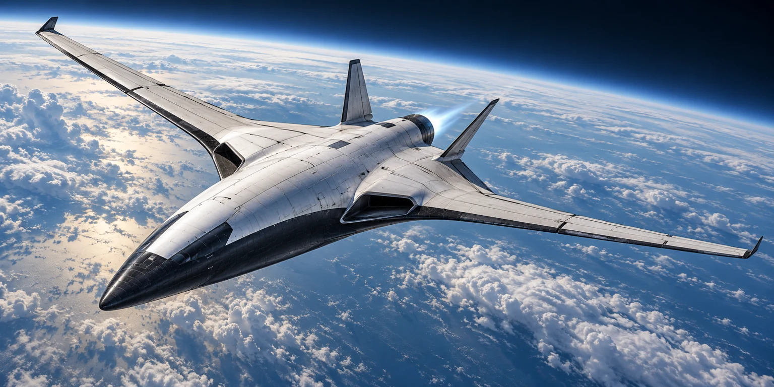
An atmosphere-refueled spacecraft designed to fly from runway to orbit and back. Test the complete mass, propulsion, trajectory and thermal budgets around a stipulated 1 GW, 500 kg Du-Cell.
PUDDLE JUMPER / finding
A trajectory can close on paper. The complete vehicle is still open.
The baseline is not ruled out by the rocket equation or finite thrust alone. A reduced-order, wing-supported ascent gives a conditional path to circular orbit. Its long hypersonic acceleration replaces much of the wasteful low-exhaust-velocity burn. This is a useful candidate to test, not a demonstrated SSTO design.
The most consequential requirements are the installed power-system mass, sustained aerodynamic performance, and the fraction of power deposited in solid hardware. No evidence establishes a 500 kg gigawatt Du-Cell, a 1,000 kg air-handling/engine plant, or the necessary hot-airframe life. Consequently, this study cannot honestly assign a validated minimum viable mass or maximum reusable payload.
Version 1 · October 17, 2026. Calculations use established mechanics and thermodynamics; reactor performance, engine maps, component allowances and aerodynamic coefficients are conditional inputs. The downloadable source distinguishes trajectory closure from complete-system feasibility.
PUDDLE JUMPER / architecture
Three flows. One closed accounting boundary.
| Flow | Material or energy | Role |
|---|---|---|
| Fusion fuel | Hydrogen prepared from collected water | Nuclear energy supply; a sub-kilogram daily inventory under the pp-I assumption. |
| Reaction mass | Stored atmospheric N₂/O₂/Ar mixture | Several tonnes expelled to carry momentum; not fusion fuel and not chemical combustion. |
| Useful power | Thermal, charged-particle, RF or electrical energy | Converted to directed exhaust energy, residual plume enthalpy and component heat. |
The current DCLXVI public project is named Dewcell. This mission brief calls its compact vehicle implementation Du-Cell; neither name implies separately validated reactor hardware. Its links to LSM, the public fusion geometry audit and fusion program (staff access) are preserved. The public audit establishes a geometric result; it supplies no measured reaction rate or net power.
The reference vehicle uses two fuselage cryogenic tanks, an electrically driven atmospheric propulsion system, a high-enthalpy air engine, magnetic high-Isp acceleration, separate hot and low-temperature cooling loops, reusable thermal protection, and runway gear. Keep nuclear fuel and product shielding distinct from the liquid-air tanks. A ground-assisted liquefier is the lower-risk early demonstrator; fully onboard refueling is a later mass-closure requirement.
PUDDLE JUMPER / fuel
Water supply is manageable. Proton-proton kinetics remain the enabling question.
For a conventional pp-I energy inventory, four hydrogen nuclei ultimately form helium; about 26.73 MeV is released per net cycle. This screen assigns 2% to escaping neutrinos and approximately 6.27 × 10¹⁴ J/kg to recoverable energy. Other branches change that fraction. [1]
ṁH = Pu / [ηc (1 − fν) qfusion]; Pu = 1 GW
| Recoverable → usable efficiency | Hydrogen at full power | Water stoichiometry¹ |
|---|---|---|
| 40% | 0.345 kg/day | 3.1 kg/day |
| 60% | 0.23 kg/day | 2.07 kg/day |
| 90% | 0.153 kg/day | 1.38 kg/day |
| 100% | 0.138 kg/day | 1.24 kg/day |
¹Water is rounded using 9 kg H₂O/kg H₂. These are consumption rates, not required total startup inventory. At 1% water mass fraction and 50% collection efficiency, the humid-air feed is only 0.003–0.007 kg/s. At DOE's representative 55.2 kWh/kg H₂ electrolyzer input, electrolysis needs roughly 0.32–0.79 kW, plus water collection, purification and gas handling. Carry fuel for dry or orbital operation. [2]
The first conventional pp step requires a weak proton-to-neutron conversion. Solar Fusion II reports S₁₁(0) ≈ 4.01 × 10⁻²⁵ MeV·barn. Removing the Coulomb barrier alone does not establish a useful reaction rate. The proposed Du-Cell mechanism must provide an independently testable rate, product spectrum, energy balance and confinement method. For illustration, S(E)/E × exp(−√(EG/E)) at E=10 keV gives σ≈4 × 10⁻⁵⁴ m². Even assigning a proton number density of 10³⁰ m⁻³ gives only about 8 W/m³ of completed-chain power in this monoenergetic screen (two initial pp reactions per chain). This is not a Maxwellian reactor model or an all-temperature bound. The reproducible calculation is included. [1]
Charged fusion products can in principle couple to fields, but pp-chain photons and neutrinos cannot be steered by a magnetic nozzle. Photon absorption, shielding and reprocessing belong in the mass and thermal budgets. No direct-coupling fraction is inferred from LSM geometry.
PUDDLE JUMPER / mass
Keep the 15-tonne baseline visible. Do not hide unassigned hardware.
| Item | Mass | Status |
|---|---|---|
| Du-Cell | 500 kg | Stipulated reactor-only mass; completeness of shielding/conversion boundary unresolved. |
| Intake, liquefier and propulsion | 1,000 kg | Aggressive allocation, not a demonstrated equipment mass. |
| Other dry systems, including payload | 8,500 kg | Illustrative breakdown below; no structural sizing or supplier mass closure. |
| Liquid air | 5,000 kg | 5.75 m³ liquid; 6.39 m³ at 10% ullage. |
| Takeoff total | 15,000 kg | 10,000 kg dry; payload included once. |
Complete dry-mass allocation and uncertainty study
| Component | Baseline kg | Illustrative low–high kg |
|---|---|---|
| Reactor | 500 | 500–500 |
| Reactor shield and containment | 0 | 500–2,500 |
| Propulsion, intake and liquefier | 1,000 | 1,500–4,500 |
| Airframe and fixed wings | 2,700 | 2,200–4,200 |
| Reusable TPS | 1,200 | 1,000–2,400 |
| Cryogenic tanks | 550 | 350–850 |
| Landing gear | 350 | 300–650 |
| Avionics, RCS and actuation | 250 | 250–600 |
| Cabin and life support | 450 | 350–850 |
| Power conversion and distribution | 900 | 700–2,500 |
| Thermal equipment | 900 | 700–3,000 |
| Payload | 500 | 500–500 |
| Growth allowance | 700 | 1,500–4,000 |
The baseline totals 10,000 kg. The study columns total 10,350–27,050 kg dry, including 500 kg payload and growth allowances. These are transparent planning scenarios, not measured ranges or calculated requirements. The zero baseline shield allocation exposes a missing boundary: it must already be inside the stipulated reactor mass or consume another allocation. Hardware growth invalidates the 15-tonne assumption unless compensated.
A defensible required mass needs reaction-product shielding calculations, magnet and power-converter designs, pressure/tank load cases, aerodynamic bending and flutter analysis, a TPS thermal model, and measured engine/liquefier specific mass. A large radiator can exceed the entire remaining mass budget by itself. Increasing the vehicle mass while holding power at 1 GW also reduces acceleration; adding mass is not automatically a solution.
Smallest supported result: the integrated baseline is a conditional trajectory candidate. There is no established smallest fully reusable vehicle in this study. The 5–100 t sweep is a screening envelope with explicitly assumed hardware, and must not be read as a certified mass optimum.
PUDDLE JUMPER / aerodynamics
Use lift where it helps. Respect the hypersonic transition.
A sailplane-inspired atmospheric phase is useful, but orbital acceleration requires a hot lifting body or spaceplane. Start structural trade studies with a fixed swept inner wing and optional folding outer panels. Conventional composite airframe structure must remain behind suitable insulation; use qualified high-temperature leading-edge and TPS systems where exposed. No conventional polymer composite is assumed to survive bare entry heating.
L = ½ρV²SCL; D = ½ρV²S(CD0 + kCL²); b = √(AR × S)
| Geometric altitude | Density kg/m³ | Speed for CL=1, S=150 m² | Wing area at Mach 0.75 |
|---|---|---|---|
| 15 km | 0.1948 | 100 m/s · M0.34 | 31 m² |
| 20 km | 0.0889 | 149 m/s · M0.5 | 68 m² |
| 25 km | 0.0401 | 221 m/s · M0.74 | 147 m² |
| 30 km | 0.0184 | 326 m/s · M1.08 | 312 m² |
| 40 km | 0.004 | 701 m/s · M2.21 | 1,301 m² |
The lift-only, CL=1/Mach-0.75 intersection is about 25 km for 150 m² at 15 t. This is an upper screening point, not an achievable service ceiling; stall margin, thrust, Reynolds number, compressibility and gust loads reduce it. A 15–20 km propulsion transition is the reference. A 150 m², aspect-ratio-12 wing spans 42.4 m; raising area to the 40 km requirement would impose a very large structural penalty. [3]
| Wing option | Benefit | Cost / selection |
|---|---|---|
| Fixed swept / moderate aspect ratio | Simpler load paths, sealing and TPS; repeatable geometry | Preferred reference for structural development; atmospheric efficiency must be checked. |
| Folding outer panels | Large low-speed area; reduced exposed span at high Mach | Hinges, locks, actuators, load concentration and hot seals; analyze 5/10/15% wing-mass penalties, not a zero-mass mechanism. |
| Retracting wings | Smaller external envelope | Internal volume competes with tanks; doors and hot seals make it a less attractive first design. |
| Rotating / variable sweep | Continuous aerodynamic trade | Moving load paths and shock/center-of-pressure changes require a full aeroelastic model. |
Cryogenic tanks belong primarily in the fuselage for the first study: wing tanks introduce bending, insulation, oxygen compatibility and moving plumbing challenges. A 100–500 kg mechanism sensitivity should be treated as additional dry mass until detailed sizing exists. Long hypersonic dwell, control authority, aeroelasticity and center-of-gravity shift remain major open items.
PUDDLE JUMPER / liquefaction
Harvest the whole mixture. Size the processing plant.
Nominal dry air is 78% nitrogen, 21% oxygen and roughly 1% argon/other gases by volume. The liquid composition and density depend on conditions; 870 kg/m³ is the stipulated screen, not a universal property. Remove water, CO₂, particulates and hydrocarbons before the cold box. Avoid cold-end blockage and uncontrolled oxygen enrichment. Nitrogen preferentially boils away during storage; monitor liquid composition, pressure and engine compatibility. [4]
Wmin = cp[Tb − T0 − T0 ln(Tb/T0)] + L(T0/Tb − 1)
Using T₀=300 K, Tᵦ=80 K, cₚ=1.005 kJ/(kg·K) and latent heat 200 kJ/kg gives 0.202 kWh/kg reversible work in a simplified one-component surrogate. A mixture equation of state is required for precision. Practical study inputs are 0.4–1.0 kWh/kg, with 0.6 kWh/kg as the reference; compressor, refrigeration, recuperation and pressure-drop performance must be measured. Industrial plants do not establish an airborne unit's mass. [4]
| Liquid production | 5 t refill | Electrical input | Plant heat rejected² |
|---|---|---|---|
| 1 kg/s | 83.33 min | 2.2 MW | 2.6 MW |
| 5 kg/s | 16.67 min | 10.8 MW | 12.9 MW |
| 10 kg/s | 8.33 min | 21.6 MW | 25.8 MW |
| 100 kg/s | 0.83 min | 216 MW | 258.1 MW |
| 463 kg/s | 0.18 min | 1,000 MW | 1,195 MW |
²Includes electrical input plus about 0.421 MJ/kg removed from feed; this is the liquefier boundary and excludes upstream reactor/converter heat. The 10.8-second energy-only refill requires 463 kg/s throughput and approximately 1.20 GW heat rejection. It is not a predicted turnaround. At 1–5 kg/s, 17–83 minutes is a useful hardware target.
ṁcapture = ρ V Aintake ηcapture; ṁliquid = min(ṁcapture, plant throughput, Pliquefier/wspecific)
| Altitude | 1 m² intake at 200 m/s, 80% capture | Time to capture 5 t, before processing |
|---|---|---|
| 0 km | 196 kg/s | 0.4 min |
| 10 km | 66.16 kg/s | 1.3 min |
| 20 km | 14.23 kg/s | 5.9 min |
| 30 km | 2.95 kg/s | 28.3 min |
| 40 km | 0.64 kg/s | 130.3 min |
At 5 kg/s, the reference cold box rejects about 12.9 MW. A 50 K mean temperature difference requires UA≈258 kW/K; at an illustrative overall U=500 W/(m²·K), exchanger surface is about 516 m² before pressure-drop, approach-temperature and fouling margins. This is internal exchange area, not intake area. A detailed multi-stream refrigeration cycle and airborne condenser design are required; no mass is inferred from this arbitrary U.
A 5 kg/s feed at 20 km and 200 m/s needs a capture area of about 0.35 m² before inlet losses. Capturing and slowing incoming air adds momentum drag of order ṁV, plus inlet and refrigeration installation drag. High-speed total-temperature rise increases the refrigeration burden. Ground collection has the easiest density, cooling and maintenance conditions; low-altitude flight is possible in principle; high-altitude collection is least favorable.
Two spherical tanks with 10% ullage have radius 0.913 m each and total surface 20.97 m². At 0.3 MPa differential pressure, 100 MPa allowable membrane stress and aluminum density 2,700 kg/m³, the ideal shell is 1.37 mm thick and 77.6 kg. This excludes insulation, supports, buckling, slosh, fittings and crash/launch loads; the baseline reserves 550 kg. At an assumed 1 W/m² heat leak, boil-off is about 9.1 kg/day; at 5 W/m² it is about 45 kg/day. Active refrigeration needs input and creates rejection heat.
For a 30-minute atmospheric climb, 5 kg/s captures 9 t in throughput terms, so the nominal inventory could be collected. At 1 kg/s it captures only 1.8 t. A coupled collection-ascent trajectory with increasing mass and intake drag has not been optimized; the integrated orbital model starts with the tanks full.
PUDDLE JUMPER / propulsion
Variable Isp is a control freedom, not free thrust.
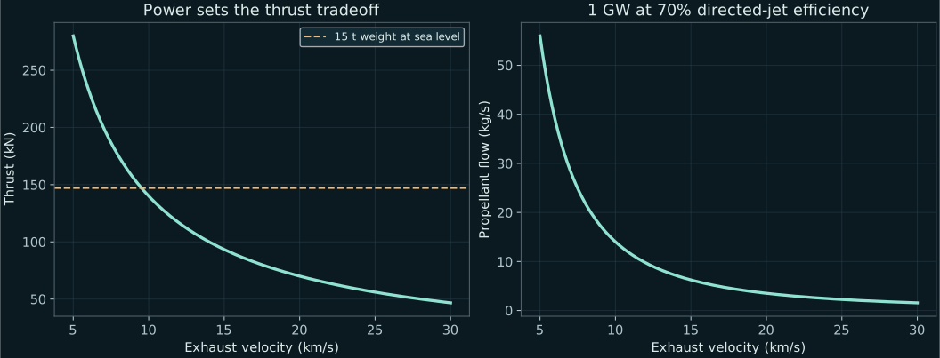
Pjet = ηPu = ½ṁve²; F = ṁve = 2ηPu/ve; Isp = ve/g₀
| Exhaust speed | Thrust | Flow | Initial thrust acceleration | 5 t burn |
|---|---|---|---|---|
| 5 km/s | 280 kN | 56 kg/s | 18.67 m/s² | 1.49 min |
| 10 km/s | 140 kN | 14 kg/s | 9.33 m/s² | 5.95 min |
| 20 km/s | 70 kN | 3.5 kg/s | 4.67 m/s² | 23.81 min |
| 30 km/s | 46.7 kN | 1.56 kg/s | 3.11 m/s² | 53.57 min |
| Mode | Candidate mechanism | Evidence boundary |
|---|---|---|
| A · atmosphere | Electric propeller / ducted fan; low reactor output | Established aerodynamic propulsion; the specific high-altitude aircraft and installed powertrain are unsized. |
| B · high thrust | Neutral or partly ionized thermal air; lower ve | Real-gas enthalpy and oxygen-compatible hot-flow hardware required. A solid-wall exchanger does not yield arbitrary exhaust temperature. |
| C · high Isp | RF / inductive heating, MPD acceleration, magnetic nozzle | Laboratory plasma technologies exist; a continuous gigawatt air engine and its 1,000 kg combined allocation do not. |
NASA's MPD summary reports continuous tests above 500 kW, with efficiency and specific impulse dependent on conditions. Ad Astra's primary test report describes 80 kW operation for 88 hours on argon with active cooling. Neither establishes this air-fed engine. RF-coupled thruster efficiency must not be substituted for reactor-to-jet efficiency. [5,6]
Fully dissociating and singly ionizing dry air costs approximately 124 MJ/kg. If that energy stays frozen in the exhaust, the ideal kinetic fractions at 5/10/20/30 km/s are about 9/29/62/78%. The stipulated 70% across all four modes is therefore an optimistic envelope, not a physical engine map. Lower-speed modes need mostly neutral flow, partial ionization or demonstrated recombination recovery. [7]
At 30 km/s, initial thrust-to-weight is only 0.317. It cannot support near-vertical ascent at 15 t, but wings can support the vehicle during a shallow acceleration. A thermal-only constant-cp estimate would require about 12,500 K even for 5 km/s; dissociation makes that estimate inadequate, underscoring the need for plasma/real-gas modeling.
Explore the power-limited envelope
This calculator updates algebraic requirements only. It does not re-optimize the trajectory.
Energy outside directed motion can leave in the plume or heat the hardware. Its partition requires measurement.
PUDDLE JUMPER / thermal
The heat must leave the vehicle.
Define Pᶠ as nuclear power, fν as neutrino escape, ηc as recoverable-to-usable conversion and Pᵤ=ηc(1−fν)Pᶠ. If Pᵤ is electricity from a 40% converter, recoverable nuclear power is 2.5 GW and converter rejection alone is 1.5 GW. If Pᵤ is directly coupled plasma/thermal power, omit that electrical loop. These are alternative architectures.
(1−fν)Pᶠ + ṁhin + Qenvironment = Pjet + ṁhout + Qradiation + Qconvection + dUvehicle/dt
Auxiliary electricity dissipated onboard appears in heat once. For 1 MW auxiliaries inside the stipulated 1 GW, engine input is 999 MW: directed energy is 699.3 MW; the other 300.7 MW is auxiliary dissipation plus non-directed engine energy. The trajectory envelope neglects that 0.1% auxiliary deduction; it does not neglect a hypothetical 1.5 GW upstream converter loss.
| Illustrative direct-coupling ledger at full thrust | Power | Requirement |
|---|---|---|
| Directed jet kinetic energy | 700 MW | 70% assumed; verify thrust, flow and complete input power. |
| Residual plume energy | 297 MW | Assume 99% of the other 300 MW leaves directly as exhaust enthalpy/radiation. |
| Solid-hardware deposition | 3 MW | Assume only 1% of non-directed energy heats hardware; this is a critical unmeasured requirement. |
| Total usable power | 1,000 MW | No extra converter heat included in this direct-coupling example. |
At 30 km/s, sending the whole 300 MW loss into 1.56 kg/s requires 193 MJ/kg of residual enthalpy. Warming regenerative coolant by 1–3 MJ/kg removes only 1.6–4.7 MW. The proposed solution therefore needs direct energy deposition into departing plasma and limited wall coupling. A conventional heat exchanger alone does not accomplish this.
Aradiating = Q / [εσ(T⁴ − Tsink⁴)]; ε=0.9
| Radiator temperature | 300 MW emitting area | 1 GW coast emitting area |
|---|---|---|
| 600 K | 45,359 m² | 151,196 m² |
| 800 K | 14,352 m² | 47,839 m² |
| 1000 K | 5,879 m² | 19,595 m² |
| 1500 K | 1,161 m² | 3,871 m² |
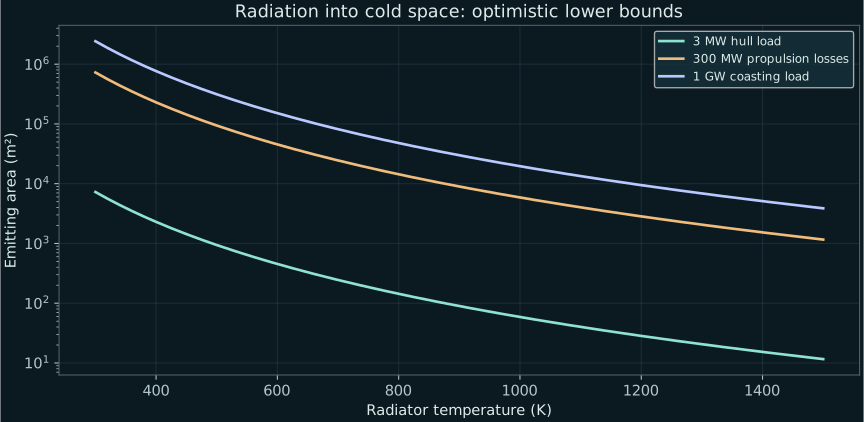
At 1,000 K, 300 MW needs 5,879 m²; at an illustrative 1–5 kg/m² emitting-area mass, that is 5.9–29.4 t before plumbing. In the direct-coupling 3 MW wall-load case, 800 K rejection needs about 144 m² and 718 kg at 5 kg/m². A separate 50 kW, 350 K loop needs about 65 m² and 326 kg under the same arbitrary area-mass assumption. Low-temperature electronics cannot simply dump heat into a hotter radiator without a heat pump and its work.
The downloadable two-node transient screen integrates a 144 m² hot loop and a 65 m² low-temperature loop through a 3,531-second full-power interval and a 90-minute coast. Both have explicitly assigned heat capacities and ideal cold-space views. Changing wall deposition from 1% to 10% of the 300 MW loss drives the hot equilibrium from about 800 K to about 1,420 K. This model exposes sensitivity; it does not qualify a material or provide the missing component network. Radiator deployment during hypersonic ascent is not assumed feasible: protected integrated surfaces, plume cooling or another demonstrated path must replace exposed deployable panels, and aerodynamic heating reduces net rejection.
In atmosphere, Q ≈ ṁcool cp ΔT offers a screening requirement: 300 MW with a 300 K air temperature rise needs about 1,000 kg/s cooling air; 3 MW needs about 10 kg/s. Finite conductance, inlet drag, radiation and high-speed stagnation temperature must be included. “Convection available” does not mean unlimited cooling.
Transient storage obeys mcp dT/dt = Qdeposited − Qrejected, with phase-change terms where appropriate. A 10-minute, 300 MW deficit stores 180 GJ: even 1 MJ/kg effective storage requires 180 t. Five tonnes of liquid air warmed to ambient absorbs only about 2 GJ before further heating, a few seconds at this load. Storage cannot cover a long orbital mission.
Coast operation must throttle or stop the reactor. At full output and zero propellant flow, even the nominally useful gigawatt needs disposal. Expelling 1 GW at 200 MJ/kg requires 5 kg/s, or 432 t/day, and creates thrust unless balanced. A 100 kW hotel/idle rejection load at 600 K still needs 15.1 m² emitting area. Restart, standby draw, residual heat and shielding remain experimental requirements. This report supplies steady/transient balance equations and requirement bounds, not a solved component-temperature network.
PUDDLE JUMPER / trajectory
Follow the vehicle all the way to circular orbit.
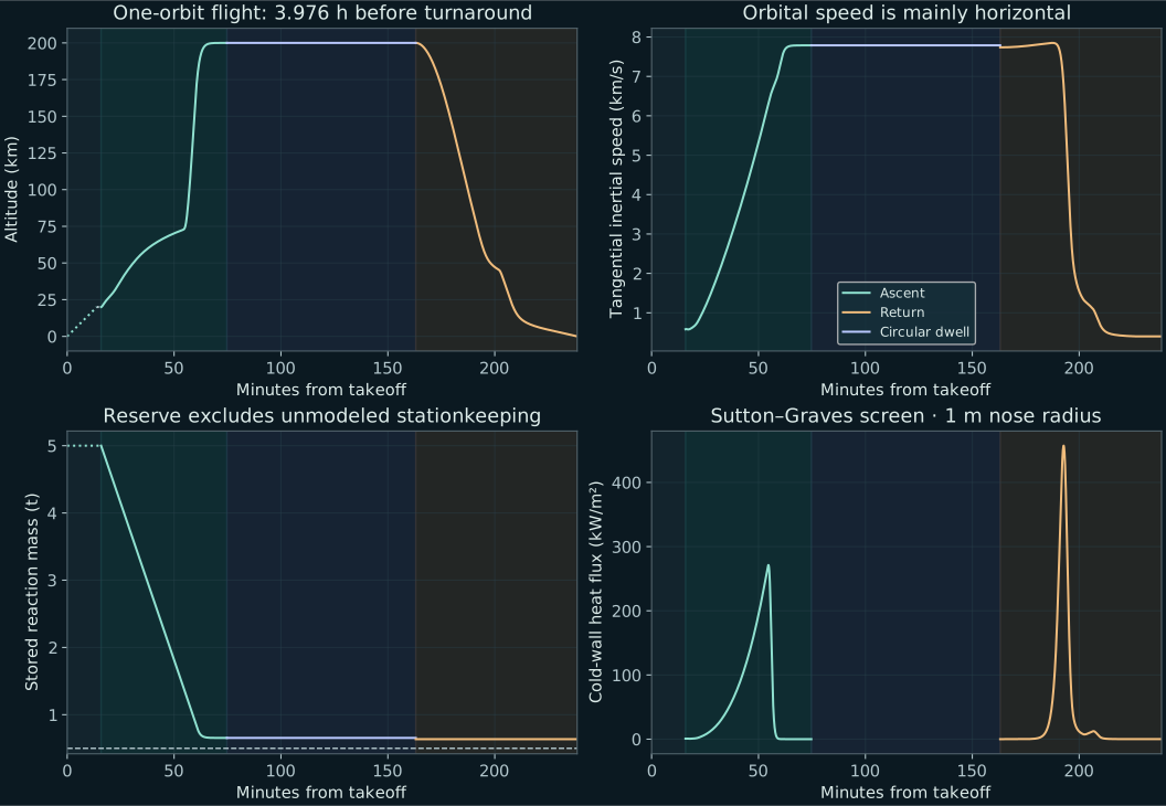
The reference integration uses central gravity, a rotating atmosphere projected at 44.366208° latitude, US Standard Atmosphere layers, mass depletion, finite variable thrust, lift and drag. It starts the rocket phase at 20 km and 250 m/s airspeed. Circular speed at 200 km is 7.788 km/s; orbital period is 88.35 minutes. Reaching 100 km alone is not orbit. [3,10]
ṙ = vr; ṽr = (Fr + L cosγ − D sinγ)/m − μ/r² + vt²/r
ṽt = (Ft − L sinγ − D cosγ)/m − vr vt/r; ṁ = −F/ve
Here r is geocentric radius; vr and vt are inertial velocity components; γ is relative to rotating air; Fr and Ft are vectored thrust components. Gravity and drag losses are integrated as forces, not added as a fixed delta-v penalty. The air-relative tangential speed subtracts Ωr cosφ. The reduced model omits three-dimensional ground-track evolution, winds, trim and actuator-rate limits.
| Integrated result | 15 t baseline | 25 t higher-drag alternative |
|---|---|---|
| Rocket ascent from 20 km | 58.85 min | 67.30 min |
| Propellant used | 4,345.4 kg | 13,578.2 kg |
| Reserve at insertion | 654.6 kg | 1,421.8 kg |
| Peak dynamic pressure | 2.86 kPa | 2.78 kPa |
| Peak ascent stagnation heating | 271.3 kW/m² | 174.8 kW/m² |
| Integrated ascent stagnation heat | 200.5 MJ/m² | 226.0 MJ/m² |
| Integrated thrust acceleration | 10.26 km/s | 14.22 km/s |
| Peak proper acceleration | 1.15 g | 1.25 g |
| Perigee / apogee | 199.977 / 200.002 km | 199.971 / 200.002 km |
| Dry / initial propellant | 10 / 5 t | 10 / 15 t (tank growth unclosed) |
| Assumed maximum high-Mach L/D | 11.4 | 3.8 |
The baseline is a conditional trajectory success. It retains 636.5 kg after the modeled deorbit impulse, above the illustrative 500 kg reserve target. Its local optimum is approximately 30 km/s exhaust throughout. Wing lift supports a shallow acceleration despite initial thrust-to-weight below one. This requires an ambitious, unvalidated hypersonic polar: CD = CD0 + 0.055CL², high-Mach CD0≈0.035 and |CL|≤0.9. It also assumes nearly free thrust vectoring and 70% jet efficiency.
The alternative triples drag and uses 11.39 km/s exhaust until 2.64 km/s airspeed, then ramps to 30 km/s by 2.84 km/s. It restores a trajectory with more reaction mass, but retains the same unverified 10 t dry mass. Fifteen tonnes of liquid air need 17.24 m³ liquid volume, or 19.16 m³ with 10% ullage. Larger tanks, intake, structure and fans must be added before treating this as an improved complete vehicle.
What the ideal rocket equation does and does not say
Δvideal = ∫ ve (−dm/m); constant ve: Δv = ve ln(m0/mf)
The 15→10 t mass ratio gives 12.164 km/s at a constant 30 km/s exhaust. Spending the first 2 t at 10 km/s and the final 3 t at 30 km/s reduces this to 9.302 km/s; spending 3 t at 10 km/s and 2 t at 30 km/s reduces it to 7.701 km/s. These ideal values do not include gravity or aerodynamic forces. The integrated model computes the actual exhaust history and state.
Atmospheric ascent and controlled return
The prescribed 15 t takeoff screen integrates 27.9 seconds and 1,166 m of ground roll to 80 m/s. Climb to 20 km takes 13.39 minutes, requiring up to 18.37 MW input and 60.8 kN thrust. Assumed fan limits are 50 kN during the roll, 65 kN in climb and 20 MW input. The endpoint still climbs at 42.2 m/s: a separate 120-second transition allowance brings it to the rocket initial condition, and is not dynamically simulated.
A 51.2 m/s impulsive deorbit maneuver uses 18.2 kg at 30 km/s exhaust and targets a 30 km osculating perigee. Coast, entry, glide and flare take 75.49 minutes. The feedback-controlled entry uses a separate assumed high-drag attitude/polar and low-altitude fan assistance. Touchdown is about 70 m/s forward and 1 m/s downward; 26.1 MJ still must be dissipated in rollout. Brakes, gear, winds and runway alignment are not sized.
Peak return heating is 457.3 kW/m², integrated stagnation heat 153.9 MJ/m², peak dynamic pressure 11.93 kPa and peak proper acceleration 2.23 g. Sutton–Graves uses a 1 m nose radius. Thin wing edges, radiative heating, catalytic effects and TPS temperatures require separate solutions. The long ascent accumulates more stagnation heat than the modeled return despite a lower peak. [9]
The return lands roughly 14,878 km downrange from the deorbit point. This two-dimensional calculation does not target the departure runway or solve orbital phasing. The atmospheric continuation above 84.852 km geopotential is approximate and cannot predict 200 km orbit lifetime or 24-hour drag makeup.
Sensitivity and numerical verification
Integrating actual throttle history gives 2.793 TJ engine input during baseline rocket ascent: 1.955 TJ directed jet kinetic energy and 0.838 TJ non-directed energy. The atmospheric climb requires 7.709 GJ fan input; landing fan assistance requires 0.072 GJ. Ground-roll power, hotel loads and upstream conversion losses are additional. The reactor must follow reduced engine demand or dispose of the unused power; constant full output throughout coasting is not assumed. The separate 3,531-second full-power thermal screen is deliberately conservative about propulsion duration and optimistic about radiation views.
| One changed input | Elapsed min | Remaining kg | Outcome |
|---|---|---|---|
| baseline | 58.85 | 655 | Orbit + 500 kg reserve |
| drag x1.5 | 64.74 | 120 | Orbit, reserve below target |
| drag x2 | 53.55 | 0 | No insertion with this policy |
| eta 0.5 | 83.62 | 219 | Orbit, reserve below target |
| eta 0.85 | 50.02 | 794 | Orbit + 500 kg reserve |
| power 0.5GW | 107.09 | 0 | No insertion with this policy |
| power 1.5GW | 42.75 | 902 | Orbit + 500 kg reserve |
| propellant 7.5t | 67.72 | 2,278 | Orbit + 500 kg reserve |
| wing 60m2 | 59.19 | 618 | Orbit + 500 kg reserve |
| wing 180m2 | 60.69 | 484 | Orbit, reserve below target |
| no lift same schedule | 1.46 | 4,864 | No insertion with this policy |
These sensitivity runs retain the published policy; failures do not prove that no other trajectory works. The 1.5 GW row excludes added reactor/converter mass; the 7.5 t propellant row excludes tank growth. The 85% efficiency row is only an algebraic sensitivity and exceeds the frozen, fully ionized air kinetic fraction at 30 km/s. A larger wing changes drag as well as lift.
| Gross t | Assumed dry t | Wing m² | Insertion / remaining kg |
|---|---|---|---|
| 5.0 | 3.33 | 40 | Yes / 352 |
| 7.5 | 5.00 | 60 | Yes / 504 |
| 10.0 | 6.67 | 80 | Yes / 602 |
| 15.0 | 10.00 | 120 | Yes / 655 |
| 20.0 | 13.33 | 160 | Yes / 407 |
| 30.0 | 20.00 | 240 | No / 0 |
| 50.0 | 33.33 | 400 | No / 0 |
| 75.0 | 50.00 | 600 | No / 19,425 |
| 100.0 | 66.67 | 800 | No / 28,902 |
The 5–100 t screen fixes dry fraction at two thirds, wing area at 8 m²/t, power at 1 GW and the optimistic polar. The 7.5 t row is the smallest numerical case retaining 500 kg at insertion, but its assumed 5 t dry mass is not a closed hardware budget. It is not a minimum viable spacecraft. The 5 t and 20 t cases miss that reserve criterion.
Terminal qualification requires |h−200 km|<1 m, |vr|<0.01 m/s and |vt−vcircular|<0.01 m/s simultaneously. Both published trajectories meet those conditions. Reducing maximum integration step from 5 to 1 second changes mass by 0.00093 kg at a common endpoint; ballistic-coast energy and angular-momentum drift are about 10⁻¹⁴. These tests establish numerical consistency, not physical validation.
PUDDLE JUMPER / cycle
Orbit time is predictable. Turnaround is a hardware question.
| Mission dwell | 15 t baseline flight | 25 t alternative flight |
|---|---|---|
| Immediate deorbit | 2.503 h | 2.622 h |
| 30-minute orbital visit | 3.003 h | 3.122 h |
| One complete 88.35-minute orbit | 3.976 h | 4.095 h |
| 24 hours in orbit | 26.503 h | 26.622 h |
Flight includes takeoff/climb, the 120-second transition allowance, finite-thrust insertion, dwell, deorbit/coast/entry and touchdown. “Immediate” means deorbit immediately after insertion to an unconstrained landing site. The 25 t cycle reuses the baseline climb timeline with scaled fan capability (roughly 31–33 MW input); its larger fan mass is unclosed. None of these durations includes waiting for a particular runway or inspection.
A 3–6 hour flight cycle is therefore compatible with this conditional short-visit/one-orbit model. It is not a demonstrated runway-to-same-runway service. The 24-hour case adds dwell only: residual reactor heat, orbit maintenance, consumables and cryogenic losses need explicit mission sizing. The tank heat-leak screen alone loses about 9–45 kg/day.
Turnaround is separate. Replacing the entire 5 t inventory takes 16.7–83.3 minutes at 5–1 kg/s plant throughput. The reference 0.6 kWh/kg input uses 3 MWh, so 1 GW supplies that energy in 10.8 seconds; processing and cooling hardware prevent treating that as a refill time. Refilling only the modeled 4.36 t expended reduces the throughput time proportionally. A 15 t tank load needs three times the full-load refill time.
Tcycle = Tflight + Tturnaround; Nflights/day ≤ 24 h / Tcycle
For illustration, a 3.98-hour one-orbit flight, a full 5 t refill at 5 kg/s, and an additional 1–4 hours of servicing give 5.25–8.25 hours per cycle, or at most 2–4 complete flights within 24 hours. These service durations are assumptions, not calculated achievable turnaround. Parallel work uses the maximum of overlapping tasks rather than their sum. Cooling, inspections, reactor restart, TPS life and runway phasing could dominate or prevent multiple flights per day. No minimum physical turnaround is established.
PUDDLE JUMPER / optimization
Optimize the installed system, not one headline parameter.
The package includes a 2,592-case algebraic screen across 5, 10, 15, 20, 30, 50, 75 and 100 t; dry fractions 0.45–0.75; 0.5–2 GW; jet efficiency 0.5–0.8; 10–30 km/s; and reactor specific power 0.1–2 MW/kg. It reports ideal Δv, reserve, initial thrust-to-weight and payload allowance under a fixed reference hardware burden. These are necessary screens, not integrated trajectories or guarantees.
mreactor = Pu / αreactor; Δvideal = ∫ve(−dm/m); mpayload = mdry − mreactor − mnonpayload hardware
At 1 GW, reactor masses are 500 kg at 2 MW/kg, 2 t at 0.5 MW/kg and 10 t at 0.1 MW/kg. Thus complete-system specific power matters more than core-only mass. The baseline's 500 kg payload is an allocation: at fixed dry mass every additional kilogram of engine, shielding, TPS or radiator reduces it by one kilogram until another constraint is reached.
Wing-area sensitivities are exposed through lift and drag; tank capacity through 870 kg/m³ plus ullage; radiator mass through temperature, emitting area and 1–5 kg/m² sensitivity; folded-wing mechanism through additional dry mass; trajectory cases vary power, mass, efficiency, drag and transition assumptions in the numerical package. A globally optimized payload design cannot be selected without validated aerodynamic and subsystem mass models.
Most defensible development configuration: ground or low-altitude air processing, a 15–20 km atmospheric transition, a robust lifting airframe that can survive a long hypersonic ascent, high-Isp acceleration while lift is available, direct energy coupling with measured low wall deposition, and deep reactor throttling in orbit. Keep a lower-Isp mode for contingency and trajectory trades; do not schedule it merely because it exists.
For the reactor premise, the reaction-rate mechanism is the first gate. Conditional on that premise, wall heat fraction and installed power-system mass dominate full-system closure; within the point-mass flight model, effective jet power per vehicle mass and hypersonic drag dominate propellant reserve. Increasing ve helps propellant economy while lengthening acceleration and thermal exposure.
PUDDLE JUMPER / roadmap
Make the next experiments small and decisive.
| Gate | Minimum useful experiment or model | Advance only when |
|---|---|---|
| 1 · Du-Cell | Independent fuel/product assay, calibrated calorimetry and complete electrical/thermal input ledger | Nuclear products, event rate and reproducible net energy agree; report null results and uncertainty. |
| 2 · Air-plasma engine | kW-class N₂/O₂/Ar thrust stand with mass-flow metrology, full power measurement, exhaust diagnostics and wall calorimetry | Measure efficiency versus ve, composition, oxygen exposure, divergence, erosion and wall heat. |
| 3 · Heat path | Electrically heated regenerative loop and magnetic/RF coupling coupon | Required heat flux leaves in the declared path; verify steady and transient temperatures. |
| 4 · Air plant | Small whole-air cold box with drying, CO₂ removal and storage composition monitoring | Record kWh/kg, kg/s, total installed mass and oxygen enrichment over repeated cycles. |
| 5 · Airframe | CFD / wind-tunnel polar, heated leading edge, cryogenic tank structure and wing lock coupon | Measured lift/drag, fatigue, flutter, thermal strain and mechanism mass support the trajectory. |
| 6 · Integrated model | 6-DOF ascent/reentry optimization with measured engine maps, thermal network, trajectory uncertainty and runway targeting | Close payload, reserves, stability, component temperatures and geographic return without hidden allocations. |
| 7 · Demonstration ladder | Atmospheric flight, then a bounded high-altitude propulsion demonstrator and progressively broader envelope | Independent review of measured performance supports each increase in energy and exposure. |
| 8 · Reuse | Repeated thermal/pressure/engine cycles and measured inspection/servicing logs | Demonstrated life and turnaround support the claimed flights per day. |
No completion date, funding amount or successful experiment is implied. A useful early paper can publish a failed mass or thermal case: it narrows the design requirements and directs the next test.
PUDDLE JUMPER / sources
Sources, reproducibility and limits.
Primary/official references support physical methods and technology anchors. All vehicle numbers, allocations and flight outcomes here are this project's calculations under the stated assumptions; no source validates Puddle Jumper.
- Adelberger et al., Solar Fusion II (2011) — pp-chain reaction inventory and weak-interaction rate.
- DOE Hydrogen Program Record 24005 (2024) — representative PEM electrolyzer electricity consumption.
- U.S. Standard Atmosphere, 1976 — layered atmosphere; the numerical package states its high-altitude extension.
- EIGA Doc 197/21: Liquid Air and Morgan et al. (2014): pilot liquid-air storage plant — process context; the 0.4–1.0 kWh/kg range is a study input and must be verified for the selected airborne cycle.
- NASA: MPD Thruster Technology (1991) — laboratory operating ranges and efficiency limitations.
- Squire et al., Steady-State Testing in the VASIMR VX-200SS Project (2021) — 80 kW/88 h argon test and cooling.
- NIST nitrogen atom and oxygen atom — thermochemical/ionization inputs.
- NASA: spacecraft thermal control — radiation and environmental heat accounting.
- Sutton and Graves, NASA TR R-376 (1971) — stagnation-point convective heating screen; not a complete wing/TPS heat solution.
- NASA Glenn: ideal rocket equation — mass depletion and the ideal Δv boundary.
The source package includes Python models, input assumptions, JSON summaries, trajectory histories, sensitivity tables, equations, figure generators and a reproduction guide. Numerical integration verification is separate from validation against flight data. This version does not solve 3-D runway phasing, structural stress, flutter, detailed plasma chemistry, radiation shielding, or a component-level transient thermal network. Those gaps prevent a minimum-mass or repeated-flight capability claim.
Visitor feedback
Comments or suggestions?
Share your thoughts on PUDDLE JUMPER. Your message goes to the site owner’s private inbox.
No sign-in required. Your message and optional contact details are saved privately for review, not published. Add an email address if you would like a reply; a response is not guaranteed. Please avoid sensitive information.